Leaderboard


 Global Moderator
Popular Content
Showing content with the highest reputation since 04/19/23 in all areas
-
Thanks banjo, I know it's funny but when I started the restoration 18 months ago I had never welded or done any form of metal shaping. I know I took Tafe courses and spent time at a professional shop to learn the skills, but for a complete novice this is a daunting task. All that said I do really enjoy it, you're right in that the process is gratifying to see how this is turning out. But it's funny to think I'm now doing the work at home, and hopefully someone will read this blog, my journey of learning and it inspires them to restore their car. Because if I can do it, well anyone can2 points
-
But as I draw closer to having the repairs to this tailgate done I am starting to think about some of the requirements/upgrades that I would like to have for this tailgate. - but more strength : I will put some extra bracing in the door frame as previously I noticed how bouncy the panel was. I have a plan for this one so stay tuned 😉 - Central locking : this will take some thinking. I'm open to suggestions - rear window wiper + nozzle : I will try get a kit and see what it looks like. I know the VW/Audi hatches have the nozzle in the spindle for the wiper so this could a neat solution - reversing camera : this should be easy enough, but I'm just thinking of a way to mount it cleanly beneath the Toyota badge. Most of these will require some modification to the tailgate, but this is the perfect time to plan for them1 point
-
weld closer to the door way to allow the fumes to escape easier & better air ventilation is always better for ur lungs... keep up the good work... love KE26 wagons! i use to have one 30yrs ago LOL... maybe i should show u my KE25 sprinter almost finished after 8yrs...1 point
-
Can’t believe I didn’t think of that! Was lying bed last night thinking about getting a bigger fan. Oh well, better welds or better lungs? Perhaps I’ll just be sensible and allow the fumes to clear before looking at the weld!1 point
-
So here is an example, I'm using 0.8mm cold rolled steel. Starting on the right I went too fast and you see the weld is proud and almost shiny. Then I slowed down and let the puddle form and you can see the change in the weld, goes flatter and the filter rod flows into the parent metal. There was no change to the settings, no change in gas, I just slowed down a little. Flipping it over, again right to left with the metal butted hard up against each other I didn't get penetration because I was too fast. but then looking right to left you can see I get good penetration once I slowed down. Hope that made sense and it helps

 1 point
 -
You can build the whole car with a handful of timber shapes and a light hammer, that's how coachbuilders worked. We do similar work building race cars, customising panels in the simplest method. It will be a work of art when the car is finished!1 point
-
Picked this up today, 64 toyota up10 700 toyoglide, original Need a hubcap if anyone can help
 1 point
 -
Most tachos, work by connecting the pulse train input wire for the tacho, to the negative terminal of the coil, which was traditionally, in a CB dissy; simply connected to the points. You could try simply connecting it to the negative terminal of your coil. If that doesn't work, then try the IGt signal. That is a nice square wave, & has some dwell information in there, as a result of the width of the pulse, which will not make any difference to the tacho reading, as it is only interested in the frequency, of the pulse train.. I notice that the ignitor in the diagram above, does have a "TAC" output, but as there is no wire colours depicted, that may make it difficult to identify, unless there are some markings on the ignitor itself. If you had access to a CRO, or a multimeter, that measures frequency, then you could probe around, until you found a signal that changes frequency with RPM. Unfortunately, I've never come across one of these Toyota ignition systems in my travels, so don't have any personal experience. Strangely, when I built the ignition system in my KE30 Corolla, years ago, I instigated a similar system, where under starting conditions, the coil is sent a signal at base ignition timing, of 10-12 degrees BTDC. Once the engine is running, the ignition system, then switches over to the electronic advance system. It does have the advantage, that the engine starts instantly always; & if your ignition system ECU & ignitor fail altogether, you can flick a switch, & get on home, in "limp mode", with just the base 10-12 degree advance. Somewhere on this forum, I described this system, years ago. I'll see if I can find it. Here it is . . . . . . Cheers Banjo1 point
-
Man ! Is that complicated. That was leading edge technology, back 30-40 years ago. However, the risk, with getting this system going; is that if & when some component in the ignition system, fails in the future; there will be a very high likelihood, of not being able to source the spare part at all, to make it work again. I also love getting olde things working again; however, there is a limit. There are plenty of trigger modules etc, that will fit inside existing dissy's, such that it appears to be "olde school", but will perform much better. Now take this guy ! I watched this video recently, & it was painful, to watch His efforts. However, He got there; & that was probably all He wanted. https://www.youtube.com/watch?v=arxOB5u9kaE Then there was this one, which many of you have watched. 10 million plus views on utube, but I loved reading the comments left by viewers ! https://www.youtube.com/watch?v=1RX_AJRbYzc Cheers Banjo1 point
-
I'm not sure how similar these systems are, they must be about the same age. This is on my early 4AGE motor- Here's the theory- Here's the diagram- Here's what it looks like- and here are the colours on mine. One wire was cut off when I got it. As you can see, the colours don't agree with the diagram, Toyota were busy making a lot of different ignition/ECU systems doing the same work around the early 1980s I think, its always very confusing. I took my tacho off the coil negative. I've never seen electronic ignition on a KE70 so I'm not much help for you I'm afraid.


 1 point
 -
Where you at? I've got both genuine brackets I could sell.1 point
-
am I missing something or is that a pump for the dry sump set up.01 point
-
I reckon the closer to 2030 and 35 we get the more watered down the UKs rules will get. I think public opinion of EVs is changing, all those early adopters have already bought one, everyone else doesn't want one or cant afford one. Lots of commentary in the USA on how they cant move used EVs off the 2nd hand lots as everyone knows they have costly risks associated, replacement battery costs etc, and you cant fix them yourself really, far as I can tell all the parts for teslas somewhat restricted to dealers etc. not to mention would you want to to try and fix them yourself, its like fixing an i-phone, possible but the change of bricking it is high and then you really are on your own as they prolly wont help you if you touch it. Everyone in AUS seems to get an elec car on leases as they have the tax incentive, and you can give it back before it needs any real maintenance.....im as DIY as it gets and I'm not lining up to buy a cheap tesla as its locked down and I cant even fix if I tried. One false move and the thing will brick itself in my driveway. The laws you suggest basically knock out an entire auto repair industry. people aren't going to like that. and how they can justify such things on the basis of environmental baffles the mind. Crushing fixable cars, moronic.1 point
-
T50 Short Shift Kits -USA Banjo1 point
-
T50 short-shift kits exist, there's one on mine, but I don't know who made it as it was on there when I fitted the gearbox. I don't notice it anymore, except for the 'Need for Speed' click-chick sound like a pump-action shotgun.1 point
-
Well, its good that the advance is much better, but 110psi is pretty bad for an engine. The usual story is to pour a teaspoon of engine oil down a spark plug hole and redo the compression test a couple of minutes later. The theory is that the oil sits on the rings and helps seal them to the bore, so any increase in compression is the result of worn rings being sealed. If it doesn't hit over 150psi (and I reckon that's unlikely!) then the leakage is through the valves being burnt. Ring job, expensive and complicated.. Valve job, simpler and much cheaper. The tricky bit is the amount of oil to put in... enough to flow across the piston (so do it on a warm engine) and get onto the rings, but too much will occupy combustion volume and put the compression readings up anyway. I've never done it, I usually take the head off and grind the valves, and at the same time I can see the lip on the bore and feel the slop in the pistons from worn rings. Do the valve clearances before you ever take a head off, the gaps can wear away until the pushrod starts to hold the valve off the seat and you lose compression. That's the only problem with the inlets, but hot combustion gases going out a tiny gap past an exhaust valve burns the valve and seat away quickly. Certainly 180psi will give you a much more powerful motor than 110psi! The fuel economy should improve now, 52deg is going to help that, 7.0 to 7.5L/100km would be good, and under 7 on a trip. The solution to the plug colour may appear later, its a puzzle..1 point
-
Yes, that's a much better advance curve, you should have the whole 36deg on by 3500rpm. The K motors will take more advance than that, its just a matter of what fuel you can buy and how much advance you can give it before it starts to lose power or knock. The plug colours are interesting, I don't know why they are in piston pairs like that. I wonder if 2 and 3 have an inlet air leak around the exhaust port in the middle and are running lean? Check the bolt tightness along the manifolds just in case. Is there one of those air pump/pollution lines run into the inlet manifold in the middle? Otherwise it is a richness problem with 1 and 4, even harder to explain! maybe a misfire on 1 and 4 is making them black.1 point
-
There is a pretty easy way to check the camshaft timing, without removing the timing chain cover; which is a bit hard to do, with the engine installed. Remove all the spark plugs, & the oil filler cap, & the dissy HT cover. Place a mark on the dissy aluminum base edge, where no: 1 spark plug lead connects to the spark plug. Rotate the engine until the crankshaft pulley "timing mark" lines up with the corresponding mark, on the timing chain cover. If the dissy rotor is out 180 degrees, then rotate the crankshaft an extra full turn, until the timing marks aligned, again. This should be T.D.C. No: 1 cylinder. Place a long screwdriver down no: 1 spark plug hole, & rock the crankshaft back & forth, to confirm that the piston, is right at the top of the travel. If it is, then your camshaft timing, is probably all good. There are a couple of things that could be amiss, if it is not at TDC, that may not be a result of a camshaft chain alignment being an issue. eg: The engine at sometime in it's life has had a timing chain cover, or a crankshaft pulley fitted, that originally came from a 5K engine, which had the marks in slightly different positions. Once you have determined that the no: 1 piston, is at TDC, you can rock the crankshaft back & forth, & looking down the oil filler hole, you should see that both inlet & exhaust rocket arms are clear of the valves. A penlite torch, often assists with this test, or alternatively remove the rocker cover. When you have determined everything is OK, then turn the crankshaft, "anti-clockwise", until the timing mark on the pulley lines up with 10 -12 deg. BTDC. Now check that the arc on the dissy rotor, is still pointing towards no: 1 spark plug lead position. If not, then there is always the possibility, that the dissy has been inserted into the block, 1 tooth out. I hope this all proves out there is not an inherent assembly problem, & then, you can concentrate on getting the centrifugal & vacuum advance / retard settings sorted. Let us know how you go. Cheers Banjo1 point
-
The airpump is part of the emissions so you don't need that, or the cat con. Cut your losses and put a non pollution engine in it. These guys have a KE55 listed on facebook right now. Gamage Motors Corolla ke 55 parts available 0773180126 Galle1 point
-
Take a look through here, I fitted an electronic dizzy and found the advance curve to be very late. In the end I used springs I found around the house to make it work. https://www.rollaclub.com/board/topic/42407-the-girls-ke70/page/4/ https://www.rollaclub.com/board/topic/49927-how-to-fix-your-brand-new-ke-motorsport-electronic-distributor/#comment-5115941 point
-
Hi Mate ! Lots of details on here, if you go searching; regarding brake upgrades on the front of KE30/55/70 Rollas, as Rollas were never well known, for their "great braking ability" I remember reading lots a threads, when I did my front end upgrade years ago, which was a resounding success. However, it involved replacing the whole strut, LCAs, & discs & calipers. When I finished, I found I had to replace the brake master cylinder with a Mitsi Pajero one. I finished up with Corona struts, 3T Toyo adjustable top pivots, Cresida discs & calipers off to different model Cresidas; & the Pajero master cylinder. It was quite a journey, & I learnt a lot, but the end result, has proven to be reliable & trouble free. Go back & look through my posts, & you'll find a lot of info there, along with a few pics. https://www.rollaclub.com/board/topic/63524-ke-3055-brake-upgrade/#comments Cheers Banjo1 point
-
According to the PGI catalogue, yes. This does not mean they are available. COROLLA KE30, KE36, KE38, KE55 1974 - 9/1981 Part no. TT148 Bottom width 1339 Centre height 595 KE35 coupe and KE50 are different1 point
-
With much trimming and fettling I got to a point where I was happy with the patch panel. So I tacked the new peice into place Looking along the edge of the bend it still needs some work but it came out ok in the end So the next task will be to make the corner peice.

 1 point
 -
"I changed coil mitsubishi Japan 12v." OK, if you fitted a 12V coil you don't need a ballast resistor. That diagram above is for a Petronix wire, and its not how Toyota did it, but it doesn't matter for you. "Since 1year all good no worries suddenly this things happened" The system you have on the car was working, so all the components fit together properly, but something has worn out. The car runs OK when its running, so coil & distributor are fine. It doesn't start properly so the problem is most likely in the key. Find that problem! Check out the key operation like Banjo said, take the plug off the key wiring and see that you get power going to the coil on both "ignition" and "start" positions. Maybe the new key wiring has burnt out. Make sure you know which wire has 12V power when you have the key in "run" position, and which has 12V power in the "start" position. If you have a test light with a needle probe you can push it into the plug while its in the car and it will light up if there's 12V. If not, I use a multimeter and unplug the key wiring so I can read ohms on each wire. Either way, you need to understand how power flows through that ignition set above. You need it wired like this- The black and orange wire (IG2) that went to the ballast now needs to be connected straight to the coil positive. That gives power when you are driving, and I'm sure that's how they changed your wiring when you fitted the new 12V coil. The red wire (ST2) powers the coil when you are cranking the engine. That also needs to go to the coil positive, like it always has. So make sure the cranking and running wires are joined and go to the coil positive. If the new wiring contacts have burnt out you should fit a relay beside the coil. This means the key barrel wiring carries less power and won't burn in the future. Cheers

 1 point
 -
Hey all Been a while since ive been on some forums, just purchased my first ke17 corolla after being out of the corolla scene for a while. Some of you know this green machine i call Carol , shes a old girl thats ready for a makeover. Future plans. Resto and give her some spice Have the exterior period correct way Interior back to original preferably sl spec. Engine either black top 20v or built 2tg. Any other cool rollas in nsw keen to meet up one weekend


 1 point
 -
So now you know the issue was your carby get yourself a carby kit and rebuild it then you will have the original on and that should make all your idle adjustments easier to perform. A kit costs about $80. You need a clean workspace and a couple of hours and it will be done. I rebuilt the carby on my daughters 4k with zero experience I learned as I went along. It was very satisfying when i reinstalled it on the engine and it fired up first go and idled perfectly. Its been going ever since. Cheers G1 point
-
Ke20 are the longest of the Corolla lcas From memory ke20 is approx 325mm while ke30 is 310mm Unless they have a ton of adjustment they won’t be long enough and you’ll end up with positive camber. What’s the reason for wanting longer Lca’s? Just for camber?1 point
-
Hi Russell, Your best friend in this situation, is a trouble shooting light, which are cheap, & can be found at any auto supply place, or even reject & cheap shops. You simply, hook the earth clip to the chassis somewhere, & then probe at various points from the battery +ve terminal, until it all of a sudden, the voltage isn't there. There is a "master fuse link", that doesn't even look like a fuse, but is usually mounted close to the battery itself. That will show up the open circuit, very quickly. Let us know how you go, & what you find. Cheers Banjo
 1 point
 -
What a lovely work you are doing right there Wenisman, hats off to you, lovely to see that level of skills being put at work. Great to see a wagon being saved, that fuel door it's awesome.1 point
-
The base of the tail gate was templated and then I cut a new peice of steel. It was folded, shrunk on the seam and then I put it through the English wheel to get a nice crown and get into the shape of the tail gate. Then I cut the rusted bottom section off and I have tack welded the new bottom section in place. I know this tailgate is taking some time, but the light is at the end of the tunnel. Next I'll try for it back on the car to make sure the skin is good. Then I'll start fixing the frame

 1 point
 -
That was a good find. I want old ones so I will keep perusing the for sale adds.1 point
-
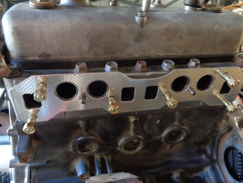
That's a genuine 7kc gasket Banjo1 point
-
Hi Ben, Sorry to hear you are having so many issues with this particular problem. My only comment at present is, that the special one piece gasket you have purchased, does not look like the the one, we have available here in Australia. The one available to us, is quite thick, & tends to take up those small gaps, between manifolds & head face. It appears from your picture to be a metal gasket, with "facing" added to it. If it is metal, one would think, it wouldn't have the ability to "absorb", small clearance descrepancies between the inlet & exhaust manifold faces. Cheers Banjo
 1 point
 -
And just like that, it's finished, slight change of plans on a few things, been on the road now for almost a year, and took 6 months of "trial and error" to get it to finally run as it should!


 1 point
 -
All went well; & the alternator upgrade, can be ticked off as successful. The only modification required, was to reshape the fan belt adjustment bracket. Below is a before & after picture. I basically flattened the standard bracket, & then sculptured away the topside, & reinforced the bracket, by infilling some of the "unused" slot in the bracket. I was even able to use the same fan belt, that was used with the old 30-40A Denso alternator. The following photo clearly shows the mounting bracket & pivot bolt assembly, without the alternator in place. The original cast "block mounting bracket", is simply inverted, & turned end for end. The new pivot bolt is 160mm long & 10mm in diameter. (the origin one was also 10mm, so no mods required there). The spacer & washer allow easy adjustment of the alternators position so the alternator pulley lines up perfectly, with the water-pump & crankshaft pullies. Here is a picture below, of it all assembled; awaiting the bottom radiator hose to be fitted. This pic below, displays the clearance at the rear of the alternator, to the engine mount. The alternator fired up, once I remembered to hook up the +D terminal, with an "idiot light", & was producing about 14.2 Volts. This particular Bosch model alternator, has a "W" terminal, which had me doing a quick Google. It apparently is a tacho output ! A number of European cars, including some VWs, obtain their tacho signal from a Bosch alternator. Cheers Banjo


 1 point
 -
So the after removing the top sleeve and then putting on a rubber sleeve from a Hilux the rear shock fits inside the rear mount. I'll secure it with a house clamp or something in the future. Because of a larger top bolt diameter and larger bushing I had to file the top mount hole to 18mm. But all up the rear shock looks good to me 🙂
 1 point
 -
Thanks Si; I will look forward to those pics. The H4 LED replacement head light bulbs arrived yesterday, & I couldn't wait until it got dark, to swap one out in the KE30, & see what the difference was. At a bit over $ 30 for a pair, it is only an experiment, & if it turns out alright, I might purchase another pair, & fit these to my Wife's Corolla or Echo. The first thing I noticed, was the very tiny plastic electric fan, at the back end of the assembly, to "keep it cool". They are tiny, & my first thought was, "I wonder how long they will last". As the fan is positioned, where the cable harness, would normally plug in, they provide an integral plug & lead. The Existing H4 headlight bulbs I had installed, were 100/90 W models, so they were already pretty bright; but I really wanted that "cool white" LED light, rather than the yellowish light, from a tungsten fillament standard bulb. Changing just one bulb, allowed me to directly compare the light outputs of both bulbs, at the same time. The result was brilliant, & the pic below, doesn't really illustrate how much better the LED bulb is. So I'll pop the battery out today, so I can get at the LHS bulb; & take it for a run tonight, out somewhere, where there are no street lights. Then, I'll start looking at "LED-anizing", all the other parking, stop & indicator lamps. Cheers Banjo


 1 point
 -
Indeed it was a long term proyect, but ever since I rented the garage, the work took of and it got a lot of momentum and its getting closer and closer to the finish. Thanks a lot for the kind words, and as you say I have a lot of updates to post Well at least after a while you'll have a pool and a garage to have fun with hahaha, so the wait it's worthy Now I have some short posts, but I tried to split the photos into diferent sections of the car while I was fixing them And we start with the rear end of the passenger side. First of all let's cut all the rotten metal, and we end up with something like this And then we have to make all this metal from scratch Little by little, with a hammer and patience each of the parts for this puzzle come to life The process is simple and the same for every part, take some measurements, find a piece of metal with that size, cut, hammer and bend to shape, and fit and refit and test fit until the shape is right. When you are happy with the fitment, and also checked with all the other parts in the vicinity, get the metal glue gun, and zapp all the parts together, then a little weld through primer and on to the next piece Test and check and weld And with that we have all the corner looking like new Onto the next part1 point
-
Hay Banjo, original paint, it needs new paint tho 40yrs takes its toll. I will take pic of inside next time for you too. But for now engine bay. Going to put battery in boot soon too. For the last 13 or so yrs I avoid driving in the rain or on wet roads. I Polished the body and fish oil under body every 12months. Always something to do... Russrolla
 1 point
 -
This is one awesome wagon I hope mine gets to this stage one day soon1 point
-
I'm just starting in restoring an ke26, just wondering how Jack is going with this ride1 point
-
Well I finally got around to finishing this little project, using a Key Fob & relay board from ebay, that are primarily designed as a "garage door replacement" item, but can find all sorts of other remote control applications. The Fob battery is a 12V A12 model, which will last for years. Just make sure when you order one, that it is either an instantaneous, or momentary model. You don't want a latching model, that keeps the horn on. Some of them can be programmed to be either, instantaneous or latching. Here is one with 2 x Fobs, 2 channel relay board & utility box for AUD 15.00 with free postage. The cheapest way, is by using a single channel/relay model, but I used a 2 channel, 2 relay one, where I paralleled the two (2) off N.O. relay contacts together, as well as the two push buttons on the Fob PCB, to make it super reliable. This is what it finished up looking like, inside the "horn bar" removable section, of the steering wheel. Bit of "blue tack" to keep all the wiring in place, & the Fob PCB is low enough profile, that is sits nicely in the steering wheel horn bar, with a bit of thick double sided tape. There is no wiring at all between the horn buttons & transmitter, to the car wiring, completely eliminating the horn ring contact & the spring loaded pin. The little relay board is simple fitted inside a small plastic utility box, sold by Jaycar / Altronics etc. There is only three wires coming out of the utility box.. Ground which is connected anywhere convenient to the car's frame. A permanent unswitched & fused 12 volt supply. The N.O. contact of the little relay board is connected to the "switched" horn wire, which can be accessed in the loom, on the plug, right at the base of the steering column. Most Rollas don't have a horn relay, & the horn button contacts switch the full horn current. Although the N.O. contact of the little relay board, depicted above, are usually rated for 10A, it might be wise to have that relay switch an automotive 30A relay up close to the horn/s proper, so there is no high current at all flowing through the little relay board & it's printed circuit board tracks, in case you get a short circuit at some time, in the horn circuitry. Works like a charm, & so happy, to have finally got rid of that "troublesome" horn contact ring, altogether. If anyone, is enticed to do similar, & needs some help, then send me a PM, & I'll do a sketch of the simple wiring options, & send it to them. Cheers Banjo


 1 point
 -
Who actually has one of these heads? Take it to China Profit?1 point
-
There is NO F#$%^&G WAY, you would ever get 100 people to put their money up for this. I'd love to have one, but seriously, you're dreaming.1 point
-
watch everyone disapear when the real prices are revealed.1 point
-
You can't just replicate the top end of this thing... timing cover, sump, upright kit, manifolds, water and oil pump and pickup. I'd guess its bottom end is built like that of an... f1 car. Then there's ignition & fuel system, crank gear, cam gear, cams, followers, valves, stems & seals, rocker cover. Shit the list goes on. You'd have to be real keen because i'd estimate five figures each. I don't mean to dash hopes but the block alone probably needs thousands spent on it. It wouldn't be running a stock crank or bearings for sure. You could expect to be building an engine from scratch.... Good Luck any how.1 point
-
After looking at some pics, I would say it is an SC14. Edit: Pic...
 1 point
 -
colin cross fevers :y: First person I have seen with the same wheels as me :S1 point
-
mine is on 13's at the moment colin cross fevers 13 x 6 +8 with 25mm spacers front and 8 mm spacers rear
 1 point
 -
Hey I'm holding an original sales brochure here and this is what is says; (Obviously weight will differ so take it with a grain of salt) Dimensions and weight: Overall length : 3980mm. (156.7 in) Overall width : 1505mm. (59.3 in) Overall height : 1405mm. (55.3 in) Kerb weight : 765kg (1685 lb) Hope that helps, it has a shitload more info too1 point


