

Banjo
-
Posts
1799 -
Joined
-
Last visited
-
Days Won
85
Content Type
Profiles
Forums
Events
Gallery
Blogs
Posts posted by Banjo
-
-
Thanks Si,
I'm sure it will all make sense, once I pull it off, & reposition the camshaft sprocket on the end of the cam. The rear of my 5K engine on the test bed, is exposed; & I have a large 360 degree wheel on the rear face of the flywheel. As it is easy to see, & was set up, with TDC no:1 cylinder being spot on; I should be able to confirm the opening on the inlet valve on No: 1 cylinder, before & after the moving of the camshaft sprocket. I will advise, once I tackle it, this evening.
The 5K engine official engine power output specs, indicate it produced . . . .
QuoteThe 1.5 L (1,486 cc) 5K was produced from 1983 through 1996. Typical output is 55 kW (74 hp; 75 PS) at 5600 rpm. Bore and stroke is 80.5 mm × 73 mm (3.17 in × 2.87 in).
As it officially, developed 74 HP / 55kW, at 5600rpm; with standard valve opening & closing times; should I initially increase or decrease the opening of the valves, to increase the power in my "desired range" of cruising; at 2500 - 3500 RPM ? ( have a 5 speed KE70 gearbox, in my KE30 ).
I'll do a bit of research, before I pick on a figure to; "test the waters".
Cheers Banjo
-
Hi Si,
I'll pull the sprocket off, before I move it; & with a protractor; measure the angular change for each positional change. The total of 8 settings, for both advance & retard, appear to each be equal. I'll then just double that number, as valve opening & closing lifts are always set as degrees of crankshaft; not camshaft. I looked on the net, for the instructions for this particular Rollmaster model, which I believe is a CS9000, but could not see one. Will have another look today. I'll post my findings here.
Many thanks !
Cheers Banjo
-
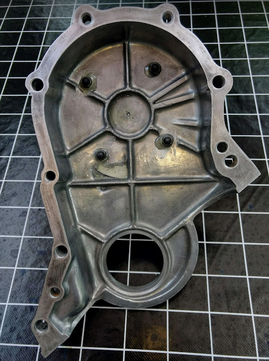
When I took the 5K engine camshaft sprocket cover off, on my 5K EFI project, to swap it over, for the one which will have the Hall sensor mounted on it, I noticed this nice new dual chain & sprocket. I'd completely forgotten that I'd replaced it with an aftermarket one, some years back, when I first set up this 5K test rig. I was always a bit miffed, with Toyota; that the two off 5K engines I had, only had, single width link camshaft chain drives, when even some of my olde 3K engines had dual chain camshaft drives. However, this new "aftermarket camshaft sprocket", was a dual chain model, & had a total off nine (9) holes, into which the location pin on the front end of the camshaft could be located. They were stamped labelled . . . .
4R -3R - 2R - 1R - 0 - 1A - 2R - 3R - 4R It appears that they represent 1-4 degrees Retard; & 1 - 4 degrees Advance, with "0" in the middle being standard/factory/design camshaft timing. The problem with selecting an advanced or retarded camshaft timing; is that only one end of the engines range is improved; whilst the other is slightly poorer.

I assume the advance, would assist, the low rev range & produce more torque; which would make sense; as 5K engines, were basically used in commercial Liteace vans, & Toyota forklifts, right up until the year 2000, I'm led to believe.
I Googled it, to see if my assumptions were right, & lo & behold, up came the following page.
https://www.rollaclub.com/board/topic/82434-4k-timing-chain/
I trust You've watched the links I posted about the FreeValve engine (earlier in this thread), which points out, that when you have "complete control" over the opening, closing; & rate of opening or closing; that you then have total control over the combustion process, which accounts for the incredible extra horsepower, they are able to extract from from a given C.C. capacity. The proof of this statement; is in the results you obtain from a race engine, with an aggressive camshaft grind; where the engine outputs more at high revs, but sounds like a olde steam engine, at a high idle.
I gather that's why a number of engine manufacturers; like Toyota, changed their valve timing to two different ranges with the VVT timing engines like our family's daily drive; Echo & Corolla engines.
I'd love to be able to adjust the camshaft timing, to provide ideal engine performance, in the 2500 - 3500 rpm range, which is where my KE30 with 5 speed gearbox & BW diff, currently sits when cruising; but it is such a "pain in the arse", to remove the timing chain cover, with the engine out, on a test bed; let alone, in the engine bay.
It is so much easier to experiment with camshaft "inlet & exhaust valve timing", on twin overhead heads, as you can just move the toothed belt, clockwise or counter clockwise, on the toothed pullies, at the front of the head.
The modified 5K camshaft sprocket cover, is almost ready to go back on the engine, as I've now added a bracket for the dual Haltech Hall Effect sensor. I will move the camshaft advance 2 degrees, & we'll see what effect that has.


The round disc, permanently fitted to; & now an integral part of the timing chain cover; is necessary, so the stainless steel bracket, mounting the Haltech dual Hall Effect sensor face is exactly square to the edge of the aluminium disc. Although the simple stainless steel bracket is only adjustable in "one plane", the centering of the Hall effect sensor, over the edge profile of the disk, is easily adjusted with 2-3 large washers, behind the disk, where the crankshaft center bolt, attaches to the crankshaft, & the crankshaft pulley.
Just awaiting, the ebay arrival of 50 off rare earth "rod" magnets; 36 off which, will be inserted into the edge of the disc; exactly 10 degrees apart. The whole exercise, is quick clean & simple, now that it is finished; & I'm pretty excited about actually running the engine, & see what the pulses look like.
This simple setup, will allow "batch fire mode", from the Speeduino ECU; but my first job after this is up & running, will be to enlarge the width of my camshaft position sensor, built into an olde Denso dissy; that will "overlap" the single pulse per rev; from the crankshaft disc, & result in a single crankshaft pulse, once per 2 revolutions of the crankshaft. That will allow full sequential control of both spark plugs & fuel injectors. Lots of fun had; bringing an olde engine up to modern day precise control of both ignition & fuel.
Cheers Banjo
-
Quote
Just imagine how worn-out a motor is when its 50years old, and then you find there are no pistons available, or bearings or seals..
My thoughts also ! Don't know what it is in our makeup, that drives us, to hold onto olde things & keep them going. Certainly not a trait with the current generation of youth, that change their mobile phones, like they change their underpants. It's called "advertising !
There are some wonderful vids on the net, of these groups of olde guys, in the UK, that spend years rebuilding olde steam tractors, after which, they take them to group meets, where they fire them up, & drive them around in circles. It's called "happiness".
If that has wet your appetite, just have a look at this, & the numbers of people who go to this show, to see all things "olde" ; & yes, there are some cars also.
Cheers Banjo
-
I watched the "blade skin & slide rail" repair, from end to end last night, & it is truly amazing, to watch, despite many bits been intentionally sped up, in places. Thank You for posting.
Cheers Banjo
-
Haven't actually tried it as yet. Some modern ECUs have an input for a knock sensor, & automatically lower the advance a little until the "knocking" is no longer detected. It allows you to get fairly "aggressive, with the advance table, while "learning" the engines characteristics, without running the risk, of doing any damage.
I need to make up a little 6kHz filter, so I can see it on the oscilloscope.
Cheers Banjo
-
So first step on a wet Saturday; yesterday in "the shed", was to transpose the "camshaft sprocket cover", onto the 5k engine.

I've swapped back over to the original 5K crankshaft pulley, as it was designed to minimise harmonic imbalance in the crankshaft itself (I believe)
This will require a longer fan belt, but that is not an issue. The main concern, & requirement, for sensing the imbedded magnets, on the outer rim of the trigger wheel, is "concentricity"; so the gap between the the outer edge of the aluminium disk, & the tip of the Haltech Hall Effect sensor, is very uniform. The use of very strong rare earth magnets, with a rating of N45 or greater, should provide greater tolerance, or slight run-out of the disk. You can take out the Hall Effect sensor, & stand above & look down the hole, in the mounting bracket; & see how well the edge (width) of the aluminium disk, is centred under the hole.

I have place several large washers, directly behind the aluminium disk, to space it slightly away from the edge of the crankshaft pulley. These washers, also allow the disk, to be moved backwards, or forward, to accommodate the thickness of the disk. I'm currently using a 6mm thick disk, but the latest disk, I have just aquired is 8mm thick; & I've now just learned, of where I can obtain a 10mm thick one, if I need it, to be able the drill holes in the edge of the disk, to accommodate a larger diameter rod rare earth magnet.

The next part of the exercise, is to create a wide camshaft position pulse, that can be logic "AND"ed, with the single North pole single on the crankshaft disk, to provide a single pulse per two (2) revolutions, of the crankshaft, for sequential ignition & inject operation.
I have three (3) options, in this regard.
(a) Use the existing cam position sensor I have created using a a "gutted", olde Denso distributor body, with dissy cap removed, & replaced by a "jam jar lid".

The pulse will simply have to be larger in width, than the single "north" pole pulse from the crankshaft.

(b) Use the Hall Effect sensor, I have fitted to the camshaft cover, detecting a rare earth magnet attached to the camshaft sprocket. This has one advantage that, both crank & cam Hall effect sensors, would be mounted on the same camshaft sprocket cover, & would look simple, neat, & very purposeful. Now the camshaft one, that is already been in place for a couple of years, has not given an "ounce of trouble". However, if it real-life, you had to get access to the magnet assembly; on the camshaft sprocket; it would be a very difficult job, to remove the camshaft sprocket cover, with the engine, in the engine bay.
(3) I've come across a reference on the net recently, of someone using the camshaft lobe tip, for driving the mechanical fuel pump, to trigger a Hall Effect device. I daresay, it would work alright, even though the lobe in the K series engines, doesn't directly point towards the middle of the mounting point opening, on the side of the block. However, & don't particularly fancy the Hall Effect sensor, operating reliably, in that very hot environment, being constantly "splashed", with hot oil.

I think, with those restrictions, the gutted dissy shell that I have already made, will be the way I go initially. Unlike the other two alternatives, "a" & "b", there is no issue with access, or being in a constant hot & oily environment. All i have to do, is maybe install a rare earth magnet, with a wider face, so the the pulse width of the cam position sensor overlaps the single "single north pole" crankshaft pulse.
Anyway, I currently will have a knock sensor attached to the unused mechanical fuel pump mounting point, so that option is out

So that's the objective for today; & then it will be time to pull the camshaft sprocket cover off, & build an "all aluminium" mounting block, for the primary, Haltech dual Hall effect sensor.
Cheers Banjo
-
Well, my new "rare earth' magnets haven't arrived as yet, but I have made a 'logic interface", for the Hall Effect sensor, to "mix" the pulses from the two (2) Hall Effect sensors, so I get the exact 36 continuous pulses per revolution, without any missing teeth, & a pulse, once per crank revolution, which is all that is needed for wasted spark operation. However, if we "AND" the camshaft pulse & the single north pole pulse on the aluminum disk, the end result is a single pulse once per 2 revolutions, which will facilitate/allow, full sequential ECU operation.

It looks so clean & simple, in practice; as there is only one (1) Hall Effect Sensor housing; but inside it actually has two (2) Hall Effect sensors, side by side, with separate outputs. One output reacts to the "35" off "South" poles, & the other to the "1" "North" pole. Not a "missing tooth"/magnet in sight, which should reduce the overhead of code, that is constantly in play; trying to detect the missing tooth.
I've had it working on the bench all weekend, & the oscilloscopes traces indicate it is working perfectly. The single camshaft pulse, per camshaft revolution, will be made slightly wider that the single crankshaft pulse that indicates where the crankshaft is in it's rotation. That single pulse signal, is in perfect synchronisation with the primary 36 pulse train, as you can see in the trace below.

Below is a full rotation of the crankshaft, showing the single pulse per revolution, with no missing teeth / magnets; in the main pulse train.

The trace indicates there are just 18 pulses per revolution (not 36 off), as the small variable speed electric motor on my bench; used for this testing, is using a smaller 150mm disk, with 18 off pulses per revolution.
Many of the missing tooth trigger wheels, have more than one missing tooth, & sometimes in two or three difference places. This is so the "synchronisation", can be achieved in less than 2 revolutions, of the crankshaft. This is primarily used when cranking the engine, to start it; to allow ignition firing, within the first revolutions of the crankshaft. If you want or need to delve into why there are so many different trigger wheel "missing teeth" variants; & you've got an hour to spare, then this webinar on utube, with Josh Stewart, is a good information source.
https://www.youtube.com/watch?v=Iv4xvBVqQ6g
I will position the aluminium trigger disk on the crankshaft, so the the single synch pulse (north pole) occurs 90 degrees before TDC No: 1 cylinder.
Hopefully, the Dual Wheel decoder, in the Speeduino ECU, will handle this arrangement perfectly. If starting the engine, becomes a serious issue, I will look at other ways to possibly synchronise the ECU with crankshaft actual position, within half a revolution, which is the best possibility, that is attainable.
P.S. The three (3) off MOC5007 IC "opto couplers" are optional; but I have used them to optically isolate the Hall Effect sensors & their 12V supply, from the 5Vdc & logic circuitry, so that any noise in the 12 volt system, is minimised. I've used this arrangement for some time, with excellent results. I could also have just carried out any logic required, for generating the two vital output pulses for the ECU, with a simple little programable microprocessor; but the logic was so simple, that it seemed much simpler, to just utilise, two (2) cheap fixed logic gate chips.
Cheers Banjo
-
Hi Jose ! Welcome aboard. Where are you located ? In Australia, there are a number of after-market fuel guage sender units available here, on ebay; primarily for the KE70.

Not sure whether the sender unit, for the KE70 is the same as that for the KE55, although they were both built in the 1979-80 era. Altezzaclub, might be able to clear that question up ?
Frankly, they are a pain in the butt, as sometimes, when the guage is not working; replacing the sender unit, does not fix the problem. The guage does not work off 12 volts, like most things in the car. There is a small regulator, behind the dash instruments, that produces a 8V, or 9V voltage, to power the fuel guage, so it's reading does not jump up & down, with the battery voltage, which is always varying. This regulator, sometimes burns out, & needs to be replaced. Happened to me, & you'll probably find a thread on this form, regarding that, if you search.
Cheers Banjo
-
I don't know what it is, that has me, so fascinated with the concept of trigger wheels, & improving the accuracy of timing of engine fuel injection, & spark timing.
I'm fascinated, that in these days of EV, & the cries of the end of ICE engines; by the continued development of the Free Valve engine, in Sweden; where the timing of each valve can be individually timed. https://www.freevalve.com/about-us/ https://www.youtube.com/watch?v=OZWeNPi2XkE
https://www.freevalve.com/freevalve-technology/ https://www.youtube.com/watch?v=XV4NavUIznc
However, the current ICE engines, & our olde K Series, have a mechanical camshaft, that dictates exactly when the valves open & shut, irrespective of whether the engine is idling; or running at 5000 rpm.
What we do have; is the ability to change the point in time, when the spark plug fires, & the compressed air & fuel mixture "explodes", & forces the piston back down. However, that ability to advance or retard the spark event, is controlled by those bob weights & tiny little springs, that lie "hidden" under the plate in our Bosch & Denso distributors. As well as that, the points in the distributor, that determine the point at which the spark plug fires, are not directly driven by the the crankshaft. In between the crankshaft, & the distributor, are two sprockets; a camshaft chain; & a set of helical gears between the distributor & the camshaft; all which develop slop, & therefore timing errors; particularly, when our 5K engines are 20-50 years olde !
It is therefore, a no brainer, to be able to time the ignition triggering directly off the crankshaft, where all that slop in camshaft & timing chain cogs, have absolutely no effect, at all.
I have a large timing disc, on the flywheel of my 5K test engine, with a strobe light. When the engine is running with the 5K dissy, you can actually see the trigger point moving about back & forth. When the engine is controlled by an ECU, with a crankshaft fed trigger signal, the strobe on the timing disk is "rock solid", & steady.
When I first started playing with this years ago, my early experiments involved using the starter motor teeth, on the flywheel; as a indication of where the engine was in it's cycle. Unfortunately, the number of teeth around the flywheel peripheral, are all; not equally divisible by 360 degrees.
The idea of fitting a separate large trigger wheel, to the opposite side of the flywheel to the clutch, is still one, I might revisit, as trigger wheels on the crankshaft pulley, are prone to damage in rally cars, & therefore avoided by many, in that sport.
So accuracy is everything, & you can have the most sophisticated & expensive ECU, but if the trigger signal feeding the ECU, is not stable or accurate, then the adage "rubbish in; rubbish out", comes to mind.
I personally don't favour the missing tooth concept, for a trigger disk. My first sojourn into this area, used a missing tooth trigger wheel. The problem is that the ECU sees the trailing edge of the tooth, before the gap, or missing tooth. From the frequency of the pulse chain, to that point, the ECU expects the next pulse to arrive at a certain duration, after the last pulse. It does this for every pulse presumably. If the pulse is not forthcoming, the ECU assumes that this is the missing tooth. The problem with this assumption; is that a missed pulse, could be resulting from an excessive air gap; or squaring of a VR signal, or a VR signal, at low rpm; & will be interpreted by the ECU as the missing tooth.
The engine, then loses its firing / injection synch.
My assertion, from experience; says that the pulse from a Hall Effect sensor, & imbedded magnet, is a much more reliable scenario, in missing tooth control arrangements.
However, wouldn't it be better, if it was possible to get the same result as a missing tooth system, that worked well, . . . . . without having a missing tooth at all.
I have been able to achieve this, because of the Haltech Hall Effect sensor I have, that actually has two Hall Effect sensors; with two outputs, in the same housing.
One sensor provides an output to "south pole" magnets faces, whilst the other sensor provides an output to "north pole" faces.
I fitted 35 magnets to my 36 "tooth" aluminium wheel, with the south poles facing the Hall effect sensor. In the 36th hole I fitted the same magnet around the other way, with the north pole facing out. So once per revolution of the crankshaft, I achieve this sync pulse, from the "north pole" sensor, without a need for the computations required by the ECU, to detect a missing tooth. However, I hear you say; that the signal from the south pole sensor still has a missing signal/tooth; because it does not produce an output when the single north pole passes the sensor. True; but the output of the south & north pole dual sensors, provide an identical type of output. If we logically "OR" these two sensor outputs in an "OR or NOR" logic gate, we achieve a continuous stream of pulses, with no missing tooth at all. However, the north pole sensor, still provides a single pulse , for synchronisation, as to exactly where the crankshaft is in it's revolution, without the need to constantly keep looking for a missing tooth.
Once I have this new aluminium trigger disk running, I'll post the CRO waveforms, & the description above will be clear to see.
The other consideration, is whether there are any existing ECU decoders, that would cater for the arrangement, I am proposing. If not, the the exercise, becomes very analytical, but not very practical. I've been a great advocate of the Speeduino, EC, designed by Josh Stewart, in Ballarat Vic.
In the decoders supplied standard with Speeduino firmware, is a decoder called a 'Dual Wheel" decoder.
https://wiki.speeduino.com/en/decoders/Dual_Wheel
It is described as follows . . .
QuoteA dual wheel trigger is one where there is a primary multi-tooth wheel combined with a secondary single pulse to provide location information. The primary input should contain no missing teeth. Both pulses can run at either cam or crank speed, but sequential operations requires that the secondary pulse is located on the cam. The design of the secondary trigger can vary (Eg a single short tooth, half-moon wheel etc), provided it only provides a single pulse per revolution. As with other arbitrary tooth count wheels, the number of teeth must evenly divide into 360 (or 720 if running at cam speed).Tooth #1 is defined to be the first tooth on the primary wheel AFTER the pulse on the secondary wheel.

This decoder suits my trigger wheel design & outputs perfectly, if you are using a batch firing ignition/injection arrangement. However, it is easy to
provide sequential ignition & injection operation, by "ANDing" the single pulse per crankshaft revolution, with an "overlapping pulse", from the camshaft positional sensor. It that way, we get a single pulse every 2 revolutions of the crankshaft, which allows "sequential" operation, of the ECU.
As soon as I get this new aluminium trigger disk built, I will try this out, as at present, I can not think of anything, that will prevent this from working.
In theory, you could actually lose altogether, the camshaft pulse per 2 off crankshaft revolutions; & simply flick a switch & run the engine in a "batch" mode.
Cheers Banjo
-
As well as bolting the aluminium disk to the "ground flat" front of the cover, I also glued it with Araldite, so there was no possiblity of any oil leaks. This is how it turned out.

Next step, was to fit it all to an olde K series block, on an engine stand, in my garage; & see how the trigger wheel looked & physically sat.

Here is a closer view of the disk & Haltech Hall Effect sensor, mounted to a temporary bracket I made, to ensure the Hall Effect sensor face, lines up perfectly with the centre of the outer edge of the 200mm aluminium disk.

It is also important, that the extended line of the Hall Effect sensor body length, passes through the center point of the disk, which it clearly does, in this case.

My previous experiments, were carried out with a 150mm dia. aluminium disk, but I chose a 200mm dia. disk this time; so that there is room to double the number of magnets to 72 off, (currently 36), so that greater resolution of engine RPM, & timing can be achieved, if required. The other consideration, is that depending on the sensitivity of the Hall Effect sensor, & the strength of the magnets, it may not be able to achieve a nice clearly defined "off" period, or gap, between pulses. Ideally, the mark/space, or on/off ratio of the on & off periods of time, should be about 50:50. Only, whilst running it, & looking at the CRO (Cathode Ray Oscilloscope) waveform, will determine that.
Ultimately, I will make the bracket, supporting the Hall Effect sensor, out of a block of aluminium, with a big hole through it for the sensor. The least amount of steel close to the sensing face of the Hall Effect sensor, will reduce the possibility of magnetic field lines from the magnets, being deflected or attracted elsewhere.
So next step, is to fit it to the 5K engine, & do some serious testing.
Cheers Banjo
-
My special rare earth magnets should arrive today. In the meantime, I've finished grinding down the outer face of the camshaft sprocket cover, & fitted the 120mm dia. aluminium disk, to provide a nice flat, firm, surface; to mount the Hall Effect sensor mounting bracket.

It worked out well. Next process, will be to mount it to the front of the engine, then fit crankshaft pulley & trigger wheel, & design & build a little mount for the Hall Effect sensor.
I've purchased a new crankshaft oil seal for the cover, & was pleased to find, they are still readily available. It turns out, the front crankshaft oil seal, on the 5K engine, was used on a variety of Toyota smaller engines; hence they are still in good supply. 3K, 4K, 5K, 7K, 2R, 3R, 5R, 2T, 3T, 4TG & 12R Toyota engines, all use this same seal.
I'll, not fit the seal, until the Hall Effect sensor bracket is designed, built, & fitted, as I'm sure the cover will be on & off numerous times, during that process. I've permanently removed the four (4) sump connecting threaded studs at bottom of this cover, & replaced them with bolts; so that the aluminium cover can be removed & replaced without having to lower the sump each time. It's a mod I've done to any K Series engine, I've worked on.
When finished, a few coats of a nice gloss enamel, will have it looking like the picture I discovered on the web, that started this little side project; & which I "coverted" so much (greatly desired or envied); I simply built my own.

Cheers Banjo
-
Whilst I wait for my high strength rare earth magnets to arrive, in the next few days, & I now have a nice clean 200mm dia. aluminium disk, with a very true edge, where the magnets, will be inserted; so it's time to mark & drill the disk out, around the edge, to insert the magnets.
Now I could sit down with a protractor & fine black felt pen, & finish up with an accumulative error, as I worked around the 360 degree disk.
However, after searching the web, I found a site where you can draw a 360 degree disc, with markings; & then print out. It allows you to stipulate the diameter of the disc, & the size of the centre hole.
QuoteYou can produce all sorts of customised things, from their base templates.

You can then save it as a pdf, & print it out, 1:1. I then cut it out, & it fitted perfectly to the disc, & was easily centred, as the centre hole lined up perfectly. I then stuck it to the aluminium disk, with some thin double sided tape, & here is the result.

It is then a simple matter of working around the edge of the disk, & marking the edge with a fine black felt pen, so I can centre pop each point, so that accurate drilling can be carried out.

As my magnet trigger wheel, will have 36 magnets, it was really easy, as 360 degrees, is obviously equally divisible, by 36.
Next step will be to stand the disk up vertically, in the drill stand, so that the holes are at right angles, to the outside edge, & that the holes length heads towards the centre point of the disk. That will result in the end of the magnet, being perfectly in parallel, with the face of the Hall Effect device. I will start it off with a small "starter" hole, & then increase the holes' diameters, until there is an interference fit, so the magnets can be pressed into the disk. I'll wait until the little N45 "rod" rare earth magnets arrive, so I can measure their diameter accurately, with my micrometer, to choose the final drill hole size, before insertion.
So far, so good !
Cheers Banjo
-
Most tachos, work by connecting the pulse train input wire for the tacho, to the negative terminal of the coil, which was traditionally, in a CB dissy; simply connected to the points. You could try simply connecting it to the negative terminal of your coil. If that doesn't work, then try the IGt signal. That is a nice square wave, & has some dwell information in there, as a result of the width of the pulse, which will not make any difference to the tacho reading, as it is only interested in the frequency, of the pulse train.. I notice that the ignitor in the diagram above, does have a "TAC" output, but as there is no wire colours depicted, that may make it difficult to identify, unless there are some markings on the ignitor itself. If you had access to a CRO, or a multimeter, that measures frequency, then you could probe around, until you found a signal that changes frequency with RPM. Unfortunately, I've never come across one of these Toyota ignition systems in my travels, so don't have any personal experience. Strangely, when I built the ignition system in my KE30 Corolla, years ago, I instigated a similar system, where under starting conditions, the coil is sent a signal at base ignition timing, of 10-12 degrees BTDC. Once the engine is running, the ignition system, then switches over to the electronic advance system. It does have the advantage, that the engine starts instantly always; & if your ignition system ECU & ignitor fail altogether, you can flick a switch, & get on home, in "limp mode", with just the base 10-12 degree advance. Somewhere on this forum, I described this system, years ago. I'll see if I can find it.
Here it is . . . . . .
QuoteCheers Banjo
-
 1
1
-
-
Man ! Is that complicated. That was leading edge technology, back 30-40 years ago. However, the risk, with getting this system going; is that if & when some component in the ignition system, fails in the future; there will be a very high likelihood, of not being able to source the spare part at all, to make it work again.
I also love getting olde things working again; however, there is a limit.
There are plenty of trigger modules etc, that will fit inside existing dissy's, such that it appears to be "olde school", but will perform much better.
Now take this guy ! I watched this video recently, & it was painful, to watch His efforts. However, He got there; & that was probably all He wanted.
https://www.youtube.com/watch?v=arxOB5u9kaE
Then there was this one, which many of you have watched. 10 million plus views on utube, but I loved reading the comments left by viewers !
https://www.youtube.com/watch?v=1RX_AJRbYzc
Cheers Banjo
-
1
-
-
I haven't completed the mods to the camshaft sprocket cover as yet, but I have sited the aluminium disk, I purchased (6mm x 120mm), where it will be located; & it looks almost, as if it was designed for this application.

However, that's a few more precious hours, to finish that off, & then remove, the radiator, to get at the front of the "test engine", to remove & replace the camshaft sprocket cover, without removing the sump. What I really need to do now, is test the concept, of a 200mm aluminium disk, with magnets facing out along the edge, rather than out the side.
So back to the A/C compressor bracket mounting points on the block, & a piece of bar, & it lines up perfectly; as the centre of the crankshaft, is in line with the bottom edge of the block, which is approximately where the compressor bracket mounting holes are. Ultimately, that Hall effect sensor, will be mounted on the cover pointing down to the edge of the disk, approximately 90 deg. from where it is in the picture below.


So before I fitted any magnets, to the "rim", of the aluminium disk; I want to ensure the disk was perfectly centred, & there was no run out. The blank disks come as just that; cut with a laser, & with no centre hole. No real issue finding the centre of the blank disc. Just 2 or 3 lines across the disk, towards the edge. Measure the length of each, & find the mid point of each line. With a right angle set-square, draw a line at right angles , at the mid-point. These 2 or 3 lines should intersect at the centre point, of the circular disk. Then carefully drill at hole at the midpoint, & carefully enlarge, until you can get a reamer in there & gently remove only enough metal, until the crankshaft centre bolt, is a nice tightish fit, so there is no lateral movement in the plate, due to the hole being bigger, than the unthreaded section of the crankshaft pulley, retaining bolt.
I went through this exercise, & finished up, with a run-out of the edge of the aluminium disk, of less than 0.5mm.
I measured this run out, with a little metal "L" bracket, clamped so that you could turn the crankshaft, & measure the gap.

Normally, you would true the disk up in a lathe. However, I don't have a lathe, but the engine to which the disk is fitted, runs. At idle; just hold a very fine file on the little shown silver bracket depicted; & because the aluminium is soft, & easy to work with; in just a few minutes, you have a perfectly concentric outer edge on the disk.
It turns out the "diametric" round rare earth magnets, are made in limited sizes, & are very expensive; & I can't find the exact size I need, available in Australia.
So initially, I'm going to press small "rod" magnets into 36 holes drilled evenly around the edge of the disk. The 200mm blank aluminium disk I purchased was not available in 10mm thickness; so I had to settle for an 6mm thick one. that should allow me, to drill & press in a 4mm dia. rare earth magnet. I'll practice, of a piece of scrap 6mm thick aluminium, before I go drilling the disk, around the periferal edge.
Here is a pic, taken of the 200mm aluminium trigger disc, from the opposite side of the engine. Now there is no water pump, & no water pump pulley, or fan blades, it certainly will "unclutter the front of the engine, directly behind the radiator. I've since found an a 200mm blank aluminium disc on Amazon, that is 8mm thick, so have ordered one; but it's coming from overseas, so will probably take a couple of weeks.

So next post, I'll either be elated, that it is working, as intended; or back to the drawing board. If it works, then the next job, will be building a Hall Sensor mount on the 120mm flat disk, on the camshaft sprocket cover, depicted in the first pic, in this post.
Cheers Banjo
-
Looks like it Pete ! If you start a new topic, it asks you to select a Forum, from the pull down list, & Marketplace"; is not in the pull-down listings.


Cheers Banjo
-
It is the contacts that fail, as the contacts approach each other; & the voltage is high; it then jumps across the gap; before the contacts actually mate.
The elements will be designed for a 220V or 240V ac voltage.
The supply voltage is an AC sinusoidal waveform. 240Vac, is the average of the sinusoidal waveform; not the maximum.
The peak voltage is 1.414 times 240Vac., or 339Vac peak. Now you see the problem, which is timing. If the contacts coming together, coincides with the peak of the hi voltage waveform; "Bang".
If you think back to pre-LED lights in our houses, when we had filament bulbs; you will remember, that bulbs "popped"; often in Winter; just as you were turning them on.
Ever remember being in a dark room in Winter, & turning a light switch on; only to see a flash behind the light switch plate ?
Filament was cold, with low resistance, & therefore drew more current. Actual point in time, at which the contacts closed, was completely arbitary.
The secret; is to switch the light on, at the zero crossing point, of the 240Vac sinusoidal waveform, where the waveform changes from being negative, to positive (effectively zero volts).

I have made it a habit of using high voltage SSRs (Solid State Relays) with zero crossing switching built in, to switch large loads that cause issues, for conventional mechanical switches.
 Typical Solid State Replay, with LED to indicate is has been "turned on", by 4-32Vdc input voltage.
So irrespective of what time you "flick the switch", to power the solid state switch (SSR); the SSR, waits until the next zero crossing of the high voltage waveform, before it switches on. As a full 50Hz mains cycle is 20milliseconds, then the longest you would ever have to wait for the light to come on, would be 10 milliseconds. You would not be able to detect this delay.
I have a whole house, built 20 years ago, where the light switches only switch 12V dc, & that 12V dc, turns on a solid state switch, which turns on the bulb.
Worked really well for 20 years, & never had to replace a bulb ever. Then along came "hi efficiency" LED light bulbs, & another problem appeared. The highly efficent LED lights, sometimes glow in the dark, as they are so efficient, that the minute leakage current, through the solid state switch "snubber", is enough to cause some LED lights to "glow". Oh technology ! ! !
https://forums.whirlpool.net.au/archive/1807796
P.S. I was in NSW recently, in a Bunnings store, & You could not find a filament bulb on the shelf. Starting to go that way in Qld. also. Soon, filament bulbs will be a thing of the past, & you'll only see them in museums.
Cheers Banjo
-
Agree with Pete completely. Find an aftermarket compressor, of comparable size. Big task, but has been done before. Suggest you search on the 4AGE website forums, as there are a number of suggestions there. Whatever way you go, you are probably still going to need the 4AGE AC adapter bracket, which ever compressor setup, You finally decide upon.
https://justjdmimports.com/product/toyota-ae86-4ag-16v-new-non-pwr-str-a-c-bracket/
Good luck !
P.S. Did you save up, for the imported short shifter ?
Cheers Banjo
-
That's Not a problem, unless they have that model cooker on the international space station; & then you have to wait 6 months until the next shuttle comes up, with a spare. Lots of coolish meals, methinks ?
That relay is cheap on ebay Cooker Relay
Only $3 - $4 & it will be here in a month from China.
MPA-S-112A

Looks like the contacts overheated & took out the relay case. As long as it hasn't melted the copper track on the printed circuit board, & the solder, you be up & cooking in no time.
Cheers Banjo
-
The single screw securing the rear of the manual centre console; just screws into a little bracket. Don't think I've got a spare one in the shed, but it wouldn't be hard to make something that allows it to be tied down securely. Doesn't have to be pretty, as it is hidden under the carpet. The front mounts are a bit doggy, unless it is tied to the underside of the dash. I've got to clean my KE30 out at the weekend, so I'll take the console off, & take a couple of pics for you, that should assist a clever person like You, to make something up suitable.
Cheers Banjo.
-
Don't worry Mate ! You can always revert to this in your back yard !

No controls on this one, except a piece of free stick, to rearrange the coals ! Can't see a Bunnings in sight, in this shot ?
P.S. Even makes you a cup of cha at the same time ! How good is that; & no electricity bill.
Must be your backyard ! It's got an olde Corolla parked up there !
Cheers Banjo
-
Talking about EV cars as we have a gripe; I watched this video from Ed China some time back, & was immediately reminded of the lots of extra safety related work & time required, to actually work on an EV. So before you can even start to work on a vehicle, there is probably 20 minutes of safety prep work required, plus the removal, after the work has been completed. This extra time, will add cost to the servicing. It certainly is an eye opener, & would certainly, remove any chance of maybe doing a quick fix on the side of the road, should you break down on a trip. Sounds to me, that with EV take-up, there might be a lot more NRMA & RACQ tilt trucks on the road.
https://www.youtube.com/watch?v=i3OcYZwMBHQ
Cheers Banjo
-
Well Fellas & gals; it looks like we have a short reprieve, before they ban our 'gas guzzlers" forever. Good read & analysis on the current "fluid state of play', on the ABC website today.
Don't Ditch Your Petrol Car Just Yet !
Cheers Banjo


 Typical Solid State Replay, with LED to indicate is has been "turned on", by 4-32Vdc input voltage.


Radiator and Fan options
in KExx Corolla Discussion
Posted
Hi Alfie,
That's a nice looking radiator. Where are you physically located ? Is that radiator you have chosen, a dual pass model ?
I note that there are some companies, supplying this Koyo radiator, complete with twin electric fans.
https://www.tf-works.com/kswap-koyo-radiator-aluminum-fan-shroud-with-spal-fans/
Depending on how you are going to drive your KE26, & where you are located, that maybe a lot of radiator, for such a small engine ?
I personally have found, that my 4KU engine, in a 2 door KE30 Corolla sedan, can drive around all day, in 25-30 deg C temperatures; in traffic, without the fan ever switching on. The ram effect of the air is sufficient to keep the engine coolant temperature in check. You may even be better off, with no stroud, & maybe just a single electric fan, under thermostatic control. It depends very much on where you are located, & the resident outside air temps, & how you intend to drive the KE26.
Cheers Banjo