Standard Relay Wiring: Difference between revisions
MedicineMan (talk | contribs) No edit summary |
MedicineMan (talk | contribs) No edit summary |
||
| Line 6: | Line 6: | ||
[[Image:Relay.jpg]] | [[Image:Relay.jpg]] | ||
[[Image:Relay Diagram.jpg]] | [[Image:Relay Diagram.jpg]] | ||
Revision as of 04:31, 23 December 2006
Standard Relay
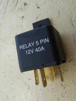
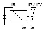
A relay is an electrical switch that is commonly used in cars to control such electrical items as your headlights and thermo fan. The relay can be broken down into 2 circuits, The control circuit and the load circuit. As the current flows through the control circuit It creates a small magnetic field which causes the load circuit switch to close. Once the switch is closed Current can then flow through the load circuit. The main idea behind the relay is so you don't have to bring high current wires inside the cabin of the car as the relay is controlled remotely. Below is an example of a generic relay and wiring diagram for it.
Wiring Diagram:
Pin 30 - 12v Power.
Pin 85 - Earth.
Pin 86 - Switch.
Pin 87 - Switched power out #1.
Pin 87A - Switched power out #2.
Article by Medicine_Man

