Tech:Electrical/Starter Motor/Reduction Type: Difference between revisions
MedicineMan (talk | contribs) No edit summary |
MedicineMan (talk | contribs) No edit summary |
||
| Line 23: | Line 23: | ||
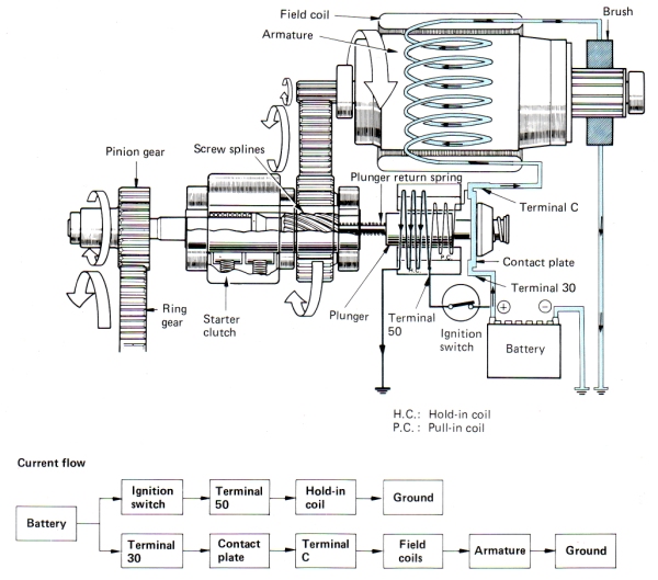
When the magnetic switch and the screw splines have pushed the pinion gear to the position where it meshes completely with the ring gear, The contact plate attached to the plunger turns the main switch on by short-circuiting the connection between terminals 30 and C. The resulting connection allows the larger electrical current to pass through the starter motor, Which causes the motor to rotate with a greater torque. The screw splines help the pinion gear mesh more securely with the ring gear. At the same time, The voltage levels at both ends of the pull-in coil become equal so that no current flows through this coil. The plunger is therefore held in position by the magnetic force exerted by the hold-in coil. | When the magnetic switch and the screw splines have pushed the pinion gear to the position where it meshes completely with the ring gear, The contact plate attached to the plunger turns the main switch on by short-circuiting the connection between terminals 30 and C. The resulting connection allows the larger electrical current to pass through the starter motor, Which causes the motor to rotate with a greater torque. The screw splines help the pinion gear mesh more securely with the ring gear. At the same time, The voltage levels at both ends of the pull-in coil become equal so that no current flows through this coil. The plunger is therefore held in position by the magnetic force exerted by the hold-in coil. | ||
[[Image:Reduction Starter Pinion Ring Gears Engaged.jpg]] | |||
Revision as of 09:36, 28 June 2007
Conventional Type
Construction
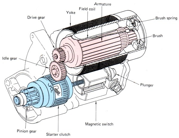
This type of starter motor contains a magnetic switch, A compact high-speed motor, Several reduction gears, A pinion gear, A starter clutch etc. The extra gears reduce the motor speed by a factor of one to three or four and transmit it to the pinion gear. The plunger of the magnetic switch directly pushes the pinion gear, Which is located on the same axis, Causing it to mesh with the ring gear. This type of starter motor generates much greater torque, In proportion to size and weight, Than the conventional type.
Operation
- 1. Ignition Switch In START Position
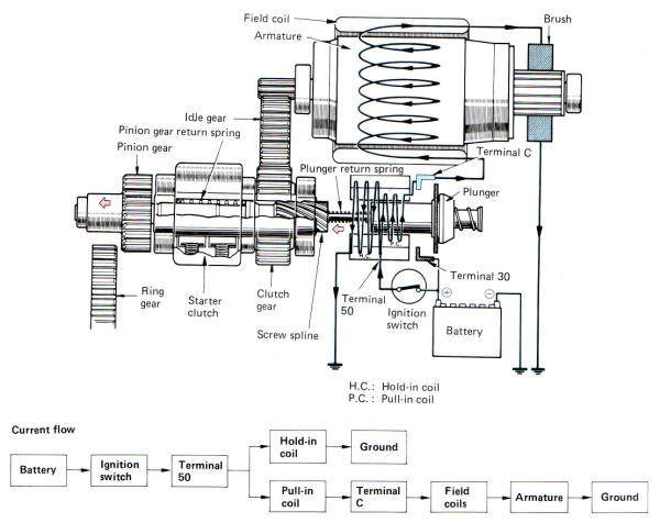
When the ignition switch has been turned to the START position, Terminal 50 passes electrical current from the battery to the hold-in and pull-in coils. From the pull-in coil, The current then flows to the field coils and armature coils via Terminal C. The motor rotates at a lower speed at this point, Since the energized pull-in coil causes a voltage drop which limits the supply of current to the motor components (The field coils and the armature). The hold-in and pull-in coils, At the same time, Set up a magnetic field which pushes the plunger to the left against the return springs. The pinion gear therefore shifts to the left until it engages with the ring gear. The low motor speed at this stage means that both gears mesh smoothly. The screw splines also help the pinion and ring gears to engage more smoothly.
- 2. Pinion And Ring Gears Engaged
When the magnetic switch and the screw splines have pushed the pinion gear to the position where it meshes completely with the ring gear, The contact plate attached to the plunger turns the main switch on by short-circuiting the connection between terminals 30 and C. The resulting connection allows the larger electrical current to pass through the starter motor, Which causes the motor to rotate with a greater torque. The screw splines help the pinion gear mesh more securely with the ring gear. At the same time, The voltage levels at both ends of the pull-in coil become equal so that no current flows through this coil. The plunger is therefore held in position by the magnetic force exerted by the hold-in coil.
Back to Starter Motor
Back to Main Page


