

Banjo
-
Posts
1933 -
Joined
-
Last visited
-
Days Won
95
4 Followers


Recent Profile Visitors


Banjo's Achievements
")


-
Hi Haydn, Another alternative; is to use a aluminium cored radiator, from a later model car, that already has an integral electric fan built in. The aluminium cores are more efficient in transferring heat; & an integral fan, is usually a better option, than adding a fan to an existing to a radiator; particularly if it's one that requires "zip-ties", through the core itself. If you scroll down through the following thread, there are some photos of my "Toyota Echo" radiator mod, to my KE-30 Rolla. https://www.rollaclub.com/board/topic/85079-aftermarket-aluminium-radiator-coreshroudfan/#comment-736509 I did it a few years back; & it's one of the better changes I've made. It is so efficient, at removing heat; that the fan rarely comes on. I hooked a pilot light up, on my dash; which shows when the fan is thermostatically switched on; so that's how I know. Cheers Banjo
-

4k/5k head (Thermostat housing compatibility)
Banjo replied to Thomas Dillon's topic in General Discussion
Hi Thomas, I've used both solutions on one of my test bed engines. The one on the aluminium spout switches the electric fan, & the one Altezzaclub suggested; I use to log the coolant temperature on an independant temperature data logger, so I can see exactly what the cooling system is doing. Cheers Banjo
-
4k/5k head (Thermostat housing compatibility)
Banjo replied to Thomas Dillon's topic in General Discussion
Hi Thomas, Yep, the one with the larger outlet, would seem to be the way to go. However, if it was me, in your shoes; I'd give both top outlet sockets a really good rub back with a rotary wire brish, on a drill, & then take a look to ensure there isn't any unseen corosion, that may compromise your project. A brand new 80 grit emery paper unside down, on a hard flat suface, show clean those gasket flange surfaces up sufficently ? Cheers Banjo -
Good morning all ! I noticed this thread was started way back in 2010; 15 years ago ! A lot has happened in that interrim period. Thank Heavens; as back then, there were limited ways of improving headlight performance; both in terms of brightness & lower power consumption. I would therefore offer this link, as a pretty good place, to learn about all that is available out there now; & being an aussie site, also has some comments about ADR requirements. https://www.stedi.com.au/blog/post/complete-led-headlight-conversion-guide#overview It's one of those subjects where there are several parameters, that affect the ultimate goal, of being able to see; further/clearer/brighter, than what our Rollas, produced in the 60s, 70s, & 80s; could ever achieve. However, if It is hard to justify the outlay, of several hundred dollars to discard lenses, reflectors, & bulbs; then there are some simple mods You can do, some of which Altezzaclub has mentioned above. The single biggest problem with early headlights; was that they were power hungry, & pulled substantial current. Some of that power was wasted as "heat", but the simple ohms law was applicable for a 36 or 40 Watt headlight bulb. Ohms law where (Current = I, Voltage = E, R = Resistance, & P = Power) says Power = Voltage x Current Therefore a dear olde 55 Watt H4 bulb with 12 volts placed across it had P/E = I; 55W/12V = 4.58 amperes current, flowing through it. We tended to always refer to the 55W rating of the bulb as being it's light output. However, the tungsten bulb was not perfect. Anyone who has tried to remove one from a headlight, after it has been on, realises it is hot. That heat is waste heat, from the tungsten filament, that never gets transformed into light. There are lots of places in the headlight circuits, that produce "voltage drops", as Altezzaclub has highlighted. Switches; relay contacts; bad connections & undersized wiring; all act like little resistors in the circuit, reducing the actual voltage that ultimately is across the bulb; & ultimately; the amount of light, that the bulb can produce. All electric power to the headlights, leaves the +ve terminal of the battery, as current, & after it has done it job; returns to the battery's -ve terminal. If You care to sit down & study this path in those horrible Toyota wiring diagrams, it is probably several metres circuit distance. The fitment of relays, directly behind the headlights, is an excellent way of reducing the heavy current path length, for the headlights, from +ve to -ve battery terminals. 30 ampere 12V automotive relays are cheap, & this mod is fairly simple, to implement. The wires that connected to the headlights originally, now operature the relays; & the relay N.O. contacts, are fed 12V directly from the battery & back, via a suitable seperate heavy 20A fuse. There are posts elsewhere on RollClub, where I have described this previously. Every light on my Corolla, is now fed power directly from the battery; & all lights are switched by relays, close to the lights. This I did, prior to LED replacement bulbs being commonly available for every size bulb on the olde Corollas. The only one You can get caught out on, is the turn indicator lights, but I believe there are now plug-in flasher units, that cater for LED bulbs. Cheers Banjo
-
4k/5k head (Thermostat housing compatibility)
Banjo replied to Thomas Dillon's topic in General Discussion
The Starlet marque has been around almost as long as the Corolla name. I know there are far more of the Starlets in Kiwi land, than here in Australia. Because they retained the rear wheel drive, for so long, & they were very popular in Japan, for road racing; that resulted in there being a lot of "after market" sports components manufactured, including suspension. Starlet bodies, also have been modernised over the years, & I believe a Starlet GTR or something special, in being planned for release in 2026 ? https://www.drive.com.au/news/2026-toyota-starlet-rumours/ There are also lots of special panels available, if You want to go all the way. The Starlet, with a wheel in each corner of the car, made it a wonderful rally platform, with little overhang, & lots of aftermarket suspension parts available. Twin OHV engines were also a popular upgrade. Not quite sure how resistant to rust, there are; compared to the KE series Corollas ? https://www.my105.com/search/details/1982-toyota-kp-starlet/057f5777-9c4b-46cd-beda-0ca0c2b0cc8f I'll leave You with this one ! https://www.tiktok.com/@twinenginecorsa/video/7374758402427309345 Cheers Banjo
-
4k/5k head (Thermostat housing compatibility)
Banjo replied to Thomas Dillon's topic in General Discussion
When engines are "this olde", I always strip every down to clean & inspect. Particular in the sump area, as it is a place, that You rarely get to inspect, whilst the engine is in the engine bay. Oil sludge build up on passage ways etc, is also a good reason to clean everything thoroughly, before reassembly. Cheers Banjo -
4k/5k head (Thermostat housing compatibility)
Banjo replied to Thomas Dillon's topic in General Discussion
Found this sump in my garage, not bolted to an engine. There appears to be a couple of sizes of sump drain nuts used by Toyota in those days. This one used a 14mm spanner, but I've got others that use a 12mm spanner. As in Thomas' photo, the threaded section, to accept the sump plug, is threaded up inside, the sump; resulting in the last bit of oil being retained in the sump, when draining it. I can see why someone; would create that little hole, in the threaded section; to drain the very last bit of "olde" oil out. Probably a better way, would be to carefully grind/file/cut out that threaded tube, & weld a new threaded section, to the outside of the sump. These threaded sections with threaded plug, are commonly available, in different sizes; at places like EFI here on the Gold Coast, in Qld. However, some may look at that picture & say; hold on, that plug is on the side of the sump; & not the bottom. Remember, the K series motors are installed; tilted to one side; so that sump drain point, is the lowest point on the sump, when installed in the engine bay. However, what caught my eye on this 5K sump, that I acquired some years ago, from a guy in Gympie, who had it in a dirt circular track midget speed car; was this other fitting on the side of the sump. It has an electrical fitting, with two pins. My first thought was maybe Toyota put some sort of heater in the sump, for models exported to very cold countries. However, the plug contacts were too small, to handle a large amount of current, so my next best guess; was that it was some sort of oil level monitor. There was a baffle inside the sump, directly above it, so I could not clearly see what it was. So out with the 4 off 8mm bolts; & a low oil level alarm contact device appeared. It appears the black rectangular piece of "plastic/bakelite" type of material, on the LHS of the picture above "floats up", & the circuit is "open circuit." It's travel is only 5-6mm, but when it drops to the bottom, the circuit is closed, & presumably lit a warning light on the dash. I did not clean this switch up, but it still works perfectly, as I put the multimeter across it, measuring ohms. This is not some aftermarket part, as the sump has a factory original flange for mounting it, & it looks like extra baffles around it, to keep the oil around it, from "sloushing" around. I dare say, it would not be used in the midget racing car; as there, the oil spends most it's time half way up the side of the sump, facing the outside of the track. So there is always something to learn; & K Series engines, are still revealing their magic ! P.S. I discovered that Toyota, , used a slight variant of the 5K oil level switch on later model Hilux, Prado, & Lexus vehicles in the USA. Slightly different; but Toyota obviously pulled out the original drawings. However, at about AUD 330 ea. out of the USA, I won't be buying one, anytime soon ! Cheers Banjo


-
4k/5k head (Thermostat housing compatibility)
Banjo replied to Thomas Dillon's topic in General Discussion
Interesting ! I don't think I've ever seen that previously ? Have to go & have a look at a sump, in the shed, that's not bolted to a engine. I'd be taking that oil pump off & dismantling it, & having a good look/inspection inside. I actually have a 4K-U engine in my daily KE-30 2 door drive. If You look at the Toyota K Series engine "yellow" bible; the power out of the 4K-U, is considerably more than the standard 4K-C; & not too much less, than a 5K. Have fun ! Cheers Banjo
-
4k/5k head (Thermostat housing compatibility)
Banjo replied to Thomas Dillon's topic in General Discussion
Hi Thomas, These are the studs, Altezzaclub, is referring to. Went through this ordeal recently on a 5K, in situ. Had to back two nuts onto each other; to be able to extract the 4 off studs from the engine, in a cramped & crowded position, before I could remove the camshaft sprocket front cover. Pain of a job, & impossibe, with the studs remaining in place. I replaced the studs with bolts, in case it has to come off again. P.S. Notice how the engine TDC timing marks on the 5K camshaft sprocket cover, are in a different position, to those on the 3K & 4K engines. A trap for those mixing & matching parts on K Series motors. I got caught years ago ! The TDC nick/indentation in the crankshaft pullies, is also in a different position, relative to the keyway in the crankshaft & pully, which is vertical at TDC on all K series engine models. There are quite a few second hand parts for K Series engines, available on ebay. I came across the following one this morning, which has to be the smallest 5K engine Toyota ever produced, at 1.5cc capacity. Cheers Banjo


-
4k/5k head (Thermostat housing compatibility)
Banjo replied to Thomas Dillon's topic in General Discussion
I've always used light sewing machine oil, like you get in those little household size tins. Like Altezzaclub says . . . spray it down towards the sides of the walls of the cylinders, so it get into the ring gaps etc. The real danger with old engines sitting around, is when the spark plugs are removed permanently for storage. Screw them back in. Plug exhaust & inlet manifold with wrag to stop air entering there, as there will always be some valves open, allowing outside moist air into the cylinder proper. If the head has been removed, smear grease into cylinder walls, & around the top edge of each piston. They can store sucessfully for years like that, as it prevents "moist air" acting on the cylinder walls. Cheers Banjo -
4k/5k head (Thermostat housing compatibility)
Banjo replied to Thomas Dillon's topic in General Discussion
Hi Thomas, Have You ever watched this guy on utube, regarding his assessment of all Toyota engines. He has a few videos, & is widely followed. Toyota Engine Assessmets In one He talks about the incredible reliability of the 1NZ-FE & 2NZ-FE engines, fitted to Yaris, Echos, & Corollas. I once looked at the possibility of the 1NZ-FE transplant to a KE series Corolla, after I purchased an Echo, for my daughter. The big problem, is it is an east/west engine, & needs some serious mods to fabricate mounting points. The other problem, is the inability to mate an inline gearbox & clutch, to the 1NZ-FE, without an adaptor; which I don't think still does not exist. I did a couple of Google searches, & strangely came across a thread on RollaClub, back in 2017, where a number of us; weighed in on this subject. I'd forgotten, all about it. You might like to have a read, at this link. https://www.rollaclub.com/board/topic/73681-cheap-4ks-maybe-not-anymore/#comment-712069 Cheers Banjo -
4k/5k head (Thermostat housing compatibility)
Banjo replied to Thomas Dillon's topic in General Discussion
Drill press is always the best. Centre punch, small drill then work your way up, with larger drills, until it's the right size for the tap, for your particular fan switch. Many of those brass switches & temp sensors, have a tapered thread. Never ever leaks ! That's why they are tapered, so they basically "jam tight", as You screw them in. Cheers Banjo -
4k/5k head (Thermostat housing compatibility)
Banjo replied to Thomas Dillon's topic in General Discussion
I have seen a thermostat cover/spout, with a threaded hole right on the top, that is the perfect place to put a electric fan "high temp" switch. (95 deg C is a usual/common fan switch temp) Anyway, I could not get hold of one, so filed a small flat on the top of the thermostat cover/spout; drilled & threaded a hole & fitted a hi temp switch. It's been in my daily drive, for years, & works like a charm. P.S. My aluminium radiator & fan is out of a Toyota Echo. Works a treat. The fan rarely comes on, when driving, as the ram effect of the air is enough to reduce the coolant temp. However, when I pull up in the driveway, after a run; the fan cuts in; & about 5-7 minutes later shuts down. Works like a dream, so the position above the thermostat, is a perfect fan control point, in the coolant flow path. Don't use a T fitting for two temp sensor. The temperature guage sensor, is best fitted to the standard guage point, on the lower thermostat housing, on the LHS, viewed from the front of the car. Works perfectly there. Cheers Banjo
-
4k/5k head (Thermostat housing compatibility)
Banjo replied to Thomas Dillon's topic in General Discussion
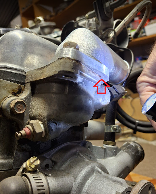
Hi Thomas, As I expected; when You reverse the standard top hose spout cover over the thermostat, it leaves a small gap, for the coolant to pour out. However, on the opposite underside of the thermostat cover/spout; the gap is not very wide at all; but there still is a gap. Because the gaps are pretty small; You could possibily cut a piece of flat sheet metal, to cover these holes, with a big round hole in the middle. You'd also need to cut a appropriate gasket either side of the flat sheet metal plate, & use gasket cement, to make sure there are no leaks. Might be an easier solution, than trying to source one of those reverse spouts, that I didn't even know existed. Cheers Banjo
-
4k/5k head (Thermostat housing compatibility)
Banjo replied to Thomas Dillon's topic in General Discussion
Hi Thomas, Superb little project ! That last link, Attezzaclub posted goes back nearly a decade & a half. After reading it again, I'm starting to feel "olde" ! Keep up the good work; & keep posting pics thereof ! Cheers Banjo


