All Activity
- Yesterday
-
Hi All, I'm not into AI as yet, as I have enough on my plate each day, to keep me very busy. MicroSoft has added AI to a number of their products. I use MicroSoft WORD every day, in my business. The latest update of Word, includes an AI function called "Co-Pilot". Basically, You ask it to produce/write something about a particular subject, & it goes away, & in a very short time, will come back, with something it has created, based on it's scouring the web, & other resources at it's disposal, where it can "learn" about what You have asked it to do. So, I'm interested in upgrading older engines, with modern day ECUs, & precision control. Of late, I've been really investigating crank & camshaft triggering systems, & currently experimenting with using a incremental rotary encoder, installed inside a gutted dissy, (thanks Taz-Rx), to produce equivalent crank & CAS pulse for a Speeduino ECU. So in Microsoft Word I simply gave Co-Pilot this task . . . . . "Write an article on using an incremental rotary encoder as a triggering system for an automotive engine" Within about 5-10 seconds, Co-Pilot produced the following short discussion, about this subject (see below) _________________________________________________________________________________________________________________________________________________________________________ Incremental Rotary Encoder as a Triggering System for Automotive Engines Innovative Solutions for Precision and Efficiency Introduction The automotive industry has seen exponential growth and technological advancements over the years. One such innovation is the use of incremental rotary encoders in engine systems to enhance performance, precision, and efficiency. This article explores the application of incremental rotary encoders as a triggering system for automotive engines, highlighting the benefits, functionalities, and implementation methods. Understanding Incremental Rotary Encoders Incremental rotary encoders are electromechanical devices that convert rotational motion into digital signals. These encoders operate by generating pulses in response to movement, which can be used to determine the position, speed, and direction of a rotating shaft. The working principle involves a disk with evenly spaced markings and a light source paired with a photodetector. As the disk rotates, the photodetector reads the markings and converts the interruptions into electrical pulses. Types of Incremental Rotary Encoders There are several types of incremental rotary encoders, each suited for specific applications: · Optical Encoders: Utilize light sources and photodetectors. Known for high precision and resolution. · Magnetic Encoders: Employ magnetic fields and Hall-effect sensors. Suitable for harsh environments due to their robustness. · Capacitive Encoders: Use capacitive sensing technology. Offer good performance with low power consumption. Application in Automotive Engines Incremental rotary encoders can play a pivotal role in enhancing automotive engine performance by providing accurate and real-time data on engine components' positions and speeds. Here’s how they can be effectively utilized: Triggering System for Engine Timing Engine timing is crucial for optimal performance, fuel efficiency, and emission control. Incremental rotary encoders can serve as excellent triggering systems for engine timing by: · Crankshaft Position Sensing: By measuring the crankshaft's position, encoders can ensure precise ignition timing and fuel injection. · Camshaft Position Sensing: Encoders can monitor the camshaft's position to synchronize valve operation with piston movement. Speed and Direction Monitoring Incremental rotary encoders can provide real-time data on the rotational speed and direction of various engine components. This information is vital for: · Engine Control Units (ECUs): ECUs can adjust engine parameters based on the data received from encoders, optimizing performance. · Diagnostics: Encoders aid in diagnosing issues related to engine speed and direction, facilitating timely maintenance interventions. Implementation in Automotive Systems Implementing incremental rotary encoders in automotive engines involves several considerations to ensure seamless integration and optimal functionality. Selection Criteria Choosing the right encoder depends on various factors: · Environmental Conditions: Opt for magnetic encoders in harsh environments due to their durability. · Resolution Requirements: Optical encoders offer high resolution, making them ideal for applications requiring precision. · Power Consumption: Capacitive encoders are recommended for systems where low power consumption is crucial. Installation and Calibration Proper installation and calibration are essential for the accurate functioning of encoders: · Mounting: Encoders should be mounted securely to prevent vibrations that could affect signal accuracy. · Alignment: Ensure that the encoder's disk is aligned correctly with the light source or magnetic sensor. · Calibration: Regular calibration checks are necessary to maintain optimal performance and accuracy. Benefits of Using Incremental Rotary Encoders The adoption of incremental rotary encoders in automotive engines offers several advantages: · Enhanced Precision: Accurate measurements of position and speed lead to improved engine timing and performance. · Real-time Data: Immediate feedback allows for timely adjustments and diagnostics. · Reduced Emissions: Optimized engine operation can contribute to lower emissions and better fuel efficiency. · Cost-effectiveness: Improved diagnostics and maintenance reduce long-term operational costs. Challenges and Solutions Despite the benefits, there are challenges associated with integrating incremental rotary encoders in automotive engines. These include: · Signal Interference: Electrical noise can interfere with the signal. Shielded cables and proper grounding can mitigate this issue. · Mechanical Wear: Continuous rotation can lead to wear and tear. Regular maintenance and high-quality materials can reduce this risk. · Temperature Variations: Extreme temperatures can affect encoder performance. Choosing encoders with suitable temperature ratings can help. Conclusion Incremental rotary encoders are revolutionizing the way automotive engines are monitored and controlled. Their ability to provide precise and real-time data on the position, speed, and direction of engine components makes them invaluable for optimizing engine performance, enhancing fuel efficiency, and reducing emissions. By understanding the types, applications, and implementation methods, automotive engineers can harness the full potential of incremental rotary encoders to drive innovation and efficiency in the automotive industry. _______________________________________________________________________________________________________________________________________________________________________ Next time I might ask it a question a little bit harder . . . . . like "How do You remove the camshaft sprocket cover, on a Toyota K Series engine, without removing the sump ?" Cheers Banjo
-
Hi John, Things are looking up, & possibilities with the guard & bonnet. To make You keep feeling good about your project, I suggest You have a look at this Corolla waggon, still in daily use in South America. It's a tradies daily drive ! https://www.curbsideclassic.com/blog/cc-capsule/cc-outtake-1977-toyota-corolla-wagon-one-hard-working-corolla/ Enjoy ! Cheers Banjo

- Last week
-
 Trent Latham joined the community
 -
 Jabbar Ramih joined the community
 -
A brief update, I caught up with Pete and now have a replacement bonnet and left guard. They'll need a bit of work. The bonnet skin looks like it's been separated from the frame and sprayed at one point, but I need to dig a bit deeper and get a good look. The adhesive isn't, so it's separated out a bit. It looks pretty straight though. The guard has two points of rust through, inside near the light and through the outer shell bottom near the door. It also has some bog in it near the blinker. Dad has sourced some tyres for me to help move it around. It's got YR 78 S12's on it and they are clearly toast so he's putting some second hand 165-12's on just to move it around. He's also getting the rims sandblasted and painted for some beer money. I expect that to be the only activity that doesn't cost me money. Also included, the two workshop manuals that were located in the boot of the car. The Scientific Publications one had absorbed so much cigarette/cigar smoke that I think I'm still coming off the nicotine high from touching it.


-
 Rjaycamilo joined the community
 -
 Willsy joined the community
 -
 Galantman74 joined the community
 -
twin 40dcoe on a 1.6 with extractors and electronic ignition or dizzy conversion from points is awesome, I fitted that to my 1977 galant 4g32 1.6
-
He has a repairable bonnet and left guard. I'm dropping in on Monday (last week was just a bit too busy). Fortunately I think I have the chrome trim from the old one.
- Earlier
-
Yesss, I'm watching zoro anime and one piece series
-
 jackkieew joined the community
 -
How did you get on with Pete?
-
 Kamlesh Aacharya joined the community
 -
 revscheck joined the community
 -
Thanks Banjo, I'll add those to my "Inspiration" folder. Looking at the rear windows I'd say these are all station wagons rather than vans. I honestly don't know how my grandfather got the smaller windows in. I do know the wood paneling was made by the carpenter at Rowntree-Hoadley (now Nestle) where my parent's both worked. Does anyone know what the difference in grille is about? Is it simply that the deluxe version had a centre channel with the logo where the regular had a sort of floating logo? The one I have has the centre channel, but dad has reminded me a few times that it's not the original. Somewhat related, the Toyota Centre for Excellence (what used to be the Altona factory) has a mint condition KE10 in the museum/collection located in the old Powertrain building. Unfortunately not generally available to the public though.
-
Hi John, Just to inspire You, here a couple of pics of a couple of restored E10 Corolla 2 door waggons I found on the net. Enjoy ! Cheers Banjo


-
I went out in the shed tonite, & found a 3K early dissy, which had the narrow, yet deep main body. This dissy was in very good condition, but I gutted it completely, so I could determine, if the incremental rotary encoder, would sit neatly inside. Ah Yes ! I even found a jam jar lid, in my wife's kitchen cupboard, (She is out tonite) that fits perfectly, like it was made for it. I would have liked a dissy body, with a replaceable ball race bearing at the base; like the one in the 4AGE distributors, instead of the phosphor bronze ones fitted to all K series engines, I believe. However, this dissy shaft & sleeve bearing are in remarkable condition, so very happy with the fact, that the two parts, manufactured, many decades apart, are so complementary. Just have to be patient now, until the Omron incremental rotary encoder, with a single "Z" pulse per revolution arrives here, & I can take it to the next stage. Cheers Banjo


-

4K-C engine stalling while down shifting, need help!
Banjo replied to Silent Icecream's topic in KExx Corolla Discussion
That's a very; very good sign, it is the clutch. You'll know instantly, once you get the full cable assembly out, & try to move the inner cable back & forth, whilst holding the outer sheath, in the other hand. I've seen them so tight, that you had to squirt WD40 down them, & wriggle the inner back & forth, before it would free up. Trick is, once You get it free up; to add copious amounts of light oil down inside the sheath, until it is free & offers no resistance. Cheers Banjo -
 This is something that has gradually become more of a situation over time. I am interested in giving this clutch cable some love! Thank you so much for your response.
 -
Yes it is a manual gearbox, it doesn't start without some throttle. I never considered the clutch being part of the issue! Thank you for your response.
-
It occurred to me, that there has to be someone out there in the big wide world, who has also seen the potential, of using an incremental rotary encoder, to basically be, an automotive "trigger wheel", & CAS signals, for an ECU's inputs. I scanned the internet, & only found one . . . https://forums.ni.com/t5/LabVIEW/Using-rotary-encoder-position-to-trigger-an-analog-pulse/td-p/2017540 If anyone reading this has come across any other similar efforts "on the web"; I'd me most grateful, if You could put a "link" in this discussion. Cheers Banjo
-
Hi All, Would anybody have a picture of a KE10 clutch pedal thats in the car? Also, a rough measurment from clutch pedal shaft to centre of gearbox tunnel? I'm currently fabricating a new tunnel and wont have my clutch pedal assembly for a few weeks. I need this to see how big the bellhousing part of the tunnel can go. Any help would be much appreciated. Cheers👍
-
Welcome Aboard ! If You want a new Carby at a cheaper price; then ebay is your friend there. They seem to all be around the $ 180 - $ 220 Here in Australia. Ebay 4AFC Carbies I'm assuming Your Rolla has a 1.6 litre engine, in it ? Cheers Banjo
-
 Ezekiel Tuipala joined the community
 -
Hey guys, just recently having issues with the Carburettor on my 1990 Toyota Corolla AE92. I have bought a 4AF Carby and it seems that the plugs will not fit. I was wondering if there was a rebuild kit or where I can get a new Carby for my 4AFC engine. Thank you!
-
4K-C engine stalling while down shifting, need help!
Banjo replied to Silent Icecream's topic in KExx Corolla Discussion
Did this start to happen, all of a sudden; where before it was working perfectly ? Or is it something, that has been getting gradually worst over time ? Altezzaclub's suggestion is the most likely; caused by the clutch cable inside the outer sheath, needing a good clean. Take the clutch cable out completely, & hang it up in a vice, by the outer sheath, at one end. Add light oil down the cable whilst moving it up & down, by hand. Put as much oil in as you can; & leave it hang overnight. Once it is free, oil it generously, & reinstall. Even if it doesn't fix your problem, it a good thing to do to your Rolla, every couple of years. There is a couple of guys on this forum, over the years, who have put in hydraulically actived clutch operation, but it involves a lot of mods. Cheers Banjo -
 Manual gearbox? Does it start with not touching the throttle? Maybe wear in the butterfly shaft, there must be a difference between having the throttle off when the motor is off and having the throttle coming off as you lift off for gear changes. Maybe the clutch is dragging so when in neutral the idle does no work, but when in gear the drag kills the motor. The simplest would be to add a little idle throttle or timing advance and lift the idle speed a couple of hundred rpm.
 -
Car starts as well as an older carby starts, then idles fine. When I drive it for over 5 - 10 minutes while slowing down and down shiftin when the revs get too low it stalls about 50% of the time. I’m trying to diagnose this problem. It idles great after I start it again. Drives fine, no misfires. Anyone got any ideas? I’d love any!
-
MkII dissy, with a "incremental" encoder, is now underway. Research yesterday, indicated two "road-blocks"; with the concept of using an "absolute", rotary encoder. 1. One was the cost. The "absolute", type of rotary encoder are far more complicated; "internally", & more difficult to manufacture; hence the increase in cost. 2. Second, was the need for a lot more electronics; & possibly a small micro processor & coding, to indentify & grab that one pulse, to utilise, as a CAS signal to the ECU. Bear in mind, that I haven't considered using this dissy in a "wasted spark" system. I have tackled the sequential control of injection & ignition initially. You can easily make a "sequential" system, operate in 'wasted spark"; but not necessarily; the other way around. Altezzaclub & I had discussed this previously; & He suggested that as the second output of the "incremental" rotary encoder was not utilised; that maybe, we could "block out, 359, of the 360 windows for the optical encoder, & just use the remaining one, & it optical sensor, as the CAS signal. I resisted this suggestion; knowing how relatively tiny the 360 "windows" will be; within a disk or ribon, fitted inside a circular structure, that is just 35mm in outside diameter. However, I've decided to take the step, & dissemble the existing incremental encoder, & take a look, & see if this is a possible alternative. I bit of reading, on the net, revealed that some incremental rotary encoders, have a single "Z" output, for internal use, to zero the processing, once per revolution. (Not the one I purchased) If that output, is accessible, & brought out, it may in fact, be utilised as a CAS signal. Fingers crossed. ! - - - - - - - - - - - - - - - - - - - - - - - - - - - - - - - - - - - - - - - - - - - - - - - - - -- - - -- - - - - - - - - - - - - - - - - - - - - - A few hours later - - - - - - - - - - - - - - - - - - - - - - - - - - - - - - - - I dissembled my incremental rotary encoder, & my suspicions were immediately realised. The disk was so small; the slots were so tiny; & there was not a single slot in sight with a light sensor, that could create a single pulse pulse per revolution. I carefully put it back together. This encoder I had ordered had 360 slots in a circle. However, you could order them, with 1000 slots; so I just cannot imagine, how narrow they must be. I was however, bolstered by the fact, that the bearing in the incremmental encoder, I've be using, was very substanial, & could work reliably in a distributor on an engine, with lots of vibrations. After a cup of coffee, I decided to see if any manufacturers, produced a incremmental rotary encoder, with a Z single pulse. There were quite a few, but they were all hundreds of dollars each. I then thought, there has got to be someone in China, making these incemental rotary encoders, with 360 pulses per revolution, & a "Z" pulse. So off to ebay, & there they were; in a variety of different pulses per revolution, but with a Z pulse once per revolution, which came out in the wiring harness/lead. Things were looking up, so I read as much as I could, about this particular brand series. They were dearer than the one I had, but I did manage, to find one, with the exact specs I wanted, in China, with Speedpak delivery, for about $ 45.00. So it's ordered, & should be here in 1-2 weeks time. When I looked up this rotary encoders outside dimensions, it is almost the same size as the current one I'm using. As I had the one here; now out of the distributor, I took it over to the shed, & found a gutted K series dissy case, which we refer to as the "narrow" one. It fitted inside, with room to spare. So don't throw out any olde K Series dissies, You might have. They may yet live; to find a new purpose in life. Cheers Banjo


-
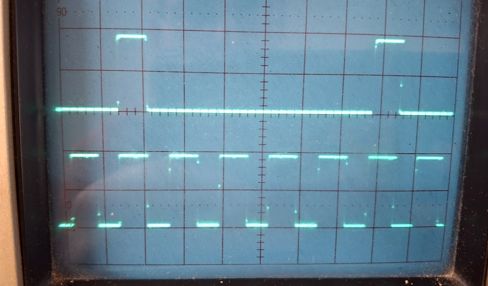
I've had some success, in the next stage of the development of a Trigger Wheel, & CAS signal, from within a K Series dissy. The Bosch K Series dissy was used, because they are physically larger in diameter, than the more common K series dissy body. The rings of rare earth magnets worked, but did present some issues. There are a couple of incremental rotary encoders used in industry; & the education industry, that provide an identical output to the rare earth magnets & Hall Sensors, but are a "drop in" item. Rotary encoders, can provide outputs, that can be used to indicate the rotational speed of the encoder; the direction of travel of the encoder; & the actual angular position, at any time. An industrial grade absolute encoder, can be quite expensived, but the small "educational" incremental ones, for teaching concepts; are less than $ 30.00 ea. As can be seen in the three pics below; they are relatively easy to mount, in the dissy. If You want to read more about encoders, in general, then head across to this link. https://en.wikipedia.org/wiki/Rotary_encoder These encoders come in a variety of models, with different numbers of pulses per single rotation. Because we are interested in angular movement of the distributor, & everything ECU wise is related to degrees BTDC etc.; I chose, & ordered; an encoder that provided 360 pulses per rotation. The encoder has two of these outputs, slightly off-set angularly, so that it is possible to work out which direction, the encoder is rotating in; although that is of no interest to us, in this dissy application, as the dissy only rotates in a clockwise direction. (more on that second output later) However, most ECUs accept pulse trains from trigger wheels, that produce pulses of 24/36/60/72 pulses per single rotation, of the crankshaft. As the dissy only rotates once per two (2) revolutions of the crankshaft, then we are only interested using 180 of those dissy encoder pulses, & we set the ECU up, as if these pulses are being derived, from the crankshaft. I then decided to see if I could divide the 180 pulses per "effective crankshaft revolution", down to one of these above common ECU trigger wheel numbers, for a crank shaft rotation. Pulse chains in electronics, can only be easily divided by whole numbers. 180 divided by those trigger wheel numbers are (180/24 = 7.5; 180/36 = 5; 180/60 = 3; & 180/72 = 2.5; 180/4 = 45. We can only easily divide by whole numbers in electrionics, so dividing the pulse train by 3 or 5 produced the equivalent of a 60 or 36 tooth crank trigger wheel. Most ECU manufacturers, advise that crankshaft trigger wheels between 24 to 60 teeth, provide best resolution. So it didn't take long to then produce these switchable trigger outputs, to an ECU. Oscilloscope grabs of the primary (360) & divided by 3 & 5 pulses, are below. I had left my single CAS magnet & Hall Effect sensor in the base of the dissy body, so do have a working system. However, the rotational encoder sits up pretty high, so I cannot create my low profile dissy, with my "jam jar" lid. Could I possibly, use that second pulse chain of the encoder, to produce a single CAS signal ? Unfortunately; not with this particular encoder, but could be possible with a absolute positional encoder, where each of the 360 pulses per rotation, creates a unique number. We could only look for just one number, & use that pulse as the CAS pulse. However, it may be simpler than that, as an absolute rotary encoder has a single pulse per revolution, that resets the counters. That may make a perfect CAS signal, if brought to the outside of the encoder. All I've got to do, is find an "absolute" rotary encoder, in a small footprint, at a reasonable price. Simon down in Tassie, is sending me up a K Series Bosch dissy, so I can then try this theory out, in practice. It may be; that ultimately, we may be able to even accomodate this angular encoder, into one of the "narrower", olde K Series dissies. All good fun ! Cheers Banjo


-
Thanks Parrot, that's incredibly helpful and Peter is less than 10 minutes from my house. I'll give him a call tomorrow during reasonable daytime hours.
-
Mechanical bits are relatively easy and cheap. Bonnets and guards are a problem that may make or break what you do, you will need to be committed. Have a talk to Peter Robinson, 17 Carinish Rd. Oakleigh South Victoria 3167. (03) 9544 1162. Everyone in Australia will direct you his way. He specialises in early Corolla's having done them for more years than you can imagine, and importantly will be your best source of parts and panels. Be VERY careful of facebook, 99% of replies you will get to wanted ads will be scammers, and everyone is after the same parts. Pete has a guy who helps him with the occasional post on his facebook page https://www.facebook.com/peterrobinsonautomotive, But as you will see, there have been a few convincing attempts to ghost his posts. He doesn't do email, you will need to call him.
-
Hi John, Just looking at those marvellous photos again, I think I spotted a silver "Shilling", sticking out from underneath the drivers seat, that may defray the resto costs a little. Then, again I might be wrong. . . . . . . . . It may well turn out to be a "sixpence piece"; . . . . . . . or; just a washer ! Cheers Banjo


