Banjo
Regular Member
-
Joined
-
Last visited
Everything posted by Banjo
-
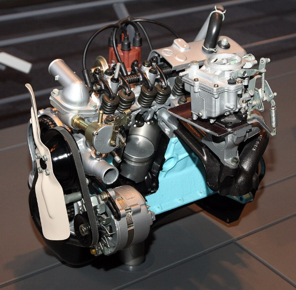
Hi John, That is simply amazing. You are obviously one of those people with a lot of patience. Many would look at that engine, in it's original state, & give up completely, before even getting started. My query, is that a 1100cc engine. I had to go & ask AI to give me all the early models & capacities. ______________________________________________________________________________________________________ There were six major versions of the Toyota K series straight-4 engine produced between 1966 and 2007. These engines were notable for their 2-valve-per-cylinder pushrod (OHV) design and non-crossflow heads. Toyota K Series Model Specifications Engine Model Capacity (cc) Capacity (L) Production Years K 1,077 cc 1.1 L 1966 – 1969 2K 993 cc 1.0 L 1969 – 1988 3K 1,166 cc 1.2 L 1969 – 1979 4K 1,290 cc 1.3 L 1977 – 1989 5K 1,486 cc 1.5 L 1983 – 1996 7K 1,781 cc 1.8 L 1983 – 2007 Key Performance Variants While the six models listed above represent the base blocks, many sub-variants existed based on fuel delivery and emissions: K-B / 3K-B: High-performance versions equipped with twin carburetors. 3K-R: A rare, race-spec 1.3L version. 4K-E / 7K-E: Fuel-injected versions (indicated by the "E" suffix). 3K-C / 4K-C: Versions designed with specific emissions controls (often for California). 3K-U / 4K-U: Japanese-spec engines with emission control systems like "Toyota Total Clean-Catalyst". The picture below is of the original 60 year olde 1077 cc K Series engine, (1966) in a cutaway format, in a Toyota museum in Japan. What interests me in this picture, is what appears to be a coolant bypass valve, between the thermostat housing & the inlet of the water pump. This could also be called a radiator bypass valve; so maybe was used to heat up the coolant quickly, from a cold start; in very cold climate countries ? ______________________________________________________________________________________________________ The original 1077cc Toyota K series engine, introduced in 1966, was the foundation of one of Toyota's most successful engine families. It was a water-cooled, inline-four, pushrod (OHV) design produced at the Kamigo plant in Toyota City. Historical Significance The "100cc Advantage": Originally intended for the under-1000cc tax class, the displacement was increased late in development to 1077cc to outperform the rival Datsun 1000. Marketing Strategy: Toyota used the slogan "The extra 100 cc gives you the edge" to highlight its performance over competitors. Corolla Launch: This engine powered the first-generation Toyota Corolla (KE10) in October 1966, playing a pivotal role in mass motorization in Japan. Technical Specifications (Standard K) Configuration: Naturally aspirated straight-four, 2 valves per cylinder (8 total). Block & Head: Cast iron block with an aluminium alloy head. Bore x Stroke: 75 mm × 61 mm. Crankshaft: Supported by five main bearings to reduce vibration and support high-speed operation. Output: Power: 60 PS (44 kW; 59 hp) at 6000 rpm. Torque: 83 N⋅m (61 lb⋅ft) at 3800 rpm. Valvetrain: High-mounted camshaft with short pushrods for improved performance Variants and Applications K-B Engine (1968–1969): A high-performance version equipped with twin carburettors, producing 73 PS (54 kW) at 6600 rpm. K-D Engine: A higher-output variant with an increased compression ratio. Key Vehicles: Toyota Corolla (KE1x series): The primary application from 1966–1969. Toyota Publica (KP3x series): The Publica SL received the more powerful K-B variant. Wikipedia +3 The 1077cc unit was eventually replaced in late 1969 by the expanded 1.2-litre 3K engine (1166cc). The History of Toyota Corollas Cheers Banjo
-
The "new age" engine, has no camshafts at all. No belts; no chains or sprockets; & can run in reverse, so you don't need a reverse gear in the gearbox. The New Age Engine Cheers Banjo
-
Yep Si ! Made in China. Following link, indicates You can have one shipped immediately. https://milexuan.en.made-in-china.com/product/ZFUTSGHcneth/China-Milexuan-Wholesale-1-5-L-Motor-Part-5K-Engine-Short-Block-for-Toyota-Carina-Corolla-Van-Liteace-Forklift.html?pv_id=1jj2s0hfeffc&faw_id=1jj2s1m40724&bv_id=1jj2s1m448be&pbv_id=1jj2s0egvb22 Note last picture in the series shows boxes & boxes of them ready to ship to Tasmania. Cheers Banjo
-
So why were K series engines just so good in their day, with so many still out there adding 1000s of klms to various cars ? I Asked this question of A.I. & You might like to read it's reply. Cheers Banjo
-
Is it possible, that the TPS, at idle rest; has the "wiper arm" on the variable resistor right at the end of it's travel. It would be better, to have the pedal at rest indicate a minimal output, & recalibrate the TPS in the ECU software, Alternatively, without the engine running; disconnect the TPS, & hook it's output across a multimeter, reading ohms. Then watch the meter as you slowly depress the throttle pedal. If the resistance does not change, the instant, the pedal is depressed slightly, then recalibrating is required. Cheers Banjo
-
Hi Allan, You'd be surprised how many modern ECUs operate that way. There is a setting in TunerStudio, which allows You to set it to Resynch, but it doesn't tell You, that sometimes the firmware code has a mind of it's own. There is another setting that allows you to set the resynch as "Weak", "Medium" or "Aggressive", but that has no effect at all. There is a Synch lamp on the TunerStudio dashboard, that is green if it is synch'd & red if it is not; but I've never seen mine ever go red. It appears that is because as far as the firmware is concerned; it is synch'd via it's prediction guessing code. Why when you've got a rock solid CAS signal once per 720 degree cycle, would you not use it at all; other than for starting the engine. Even if you resynch'd once every few minutes; using the CAS pulse, it would be better, than driving for hours & hours without using it at all. When I asked A.I. to investigate this matter, it advised that Speeduino believe their method is more accurate, as it can correct timing inbetween CAS pulses more accurately. I can understand that requirement is motor sport applications, where the acceleration can change significantly, in 2 revolutions of the crank. To ignore a guaranteed C.A.S. pulse, is not what I want or need for my 5K engine, thank you. Apparently even some of Haltech's latest model ECUs, still use the C.A.S. for resynching. In my case, I understand that the CAS pulse can jitter & become "time unstable", due to camshaft sprocket & chain, & belt drives. However, I've logically "AND'd" the camshaft one with a single CPK pulse per revolution, from the crank pulley, & the resulting pulse is absolutely "rock solid". I've not been able to find any settings in Speeduino trigger setups, that allows me to use the C.A.S. as a regular synching input. Beats me ! I'll keep on researching. At least I've got an alarm now, to alert me to the C.A.S signal no longer being there. However, that is acedemic; as the C.A.S. pulse is not being used at all, whilst the engine is running. However, it does alert me that it is no longer present; so I won't be stopping for a rest or cuppa, or photo shoot, whilst I'm crossing the Hay Plains; as I know that once the engine stops, it won't restart, without a C.A.S. pulse. I rest my case. In this case, I'd love to be "proven wrong", & that I've missed something. So if anyone has additional info or experience, regarding this matter, pleased to hear your thoughts or experience. https://speeduino.com/forum/viewtopic.php?p=74149#p74149 Cheers Banjo
-
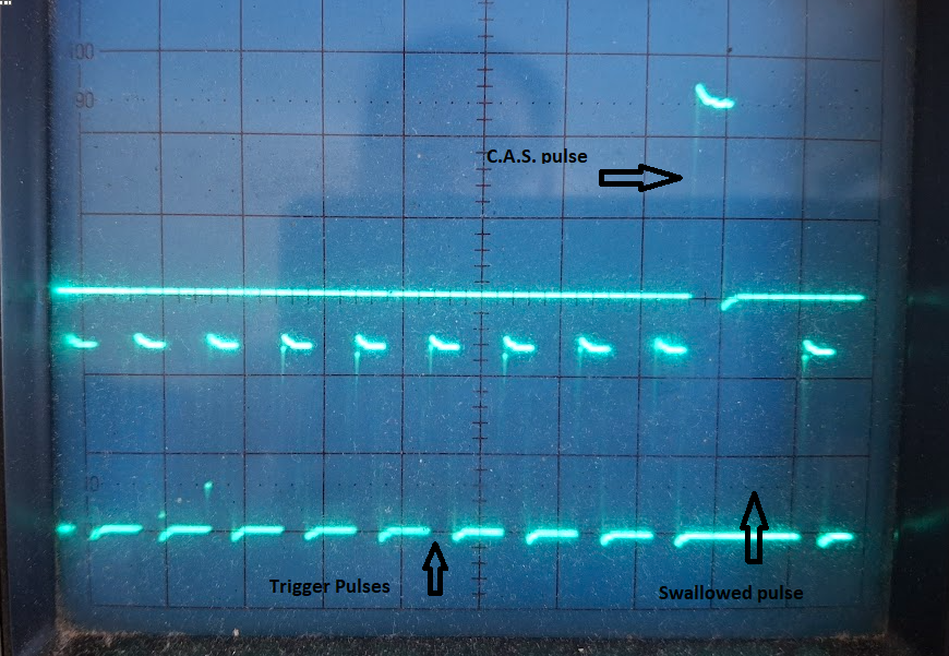
Well; pretty despondent at the moment, as my efforts to create & ignition system, using a Speeduino ECU, has not turned out the way I was wanting, with no guessing or predicting when & where the next CAS synch pulse, will arrive. So all my efforts in creating a rock solid C.A.S. pulse by logically "ANDing" it with a slightly narrower pulse from the crank, is only used to crank start the engine, after which it apparently does not get used again. I researched it wide & far, & A.I. suggested creating a missing tooth, by electronically "swallowing" the first trigger pulse after the CAS pulse. By associating the missing pulse with the CAS pulse, they suggested the ECU would be resynch'd, once every 720 degrees of rotation, of the crankshaft. I designed the electronic pulse swallower, & that worked really well. Here is what A.I. had to say about it. The rusEFI ECU does not rely on a one-time "start-and-predict" system like the Speeduino. Instead, it uses a continuous, event-driven decoding strategy that synchronizes with the Cam/Crank Angle Sensor (CAS) pulses throughout the entire engine cycle. rusEFI +1 Here is how rusEFI's synchronization logic works: Continuous Synchronization: The rusEFI Trigger Decoder evaluates every pulse from the CAS. It identifies the "synchronization point"—often a missing tooth or a specific gap—on every revolution to maintain precise timing. Predictive Offsets (Not Logic): While rusEFI uses the CAS for every revolution, it does use time-based offsets to schedule ignition. For example, if a spark is needed 10 degrees after a specific CAS tooth, it calculates the time delay based on current RPM, but it still waits for that specific tooth to pass before starting the timer. Cam vs. Crank Roles: In setups with both, the rusEFI firmware typically uses the Camshaft sensor as the primary signal to determine the 720-degree engine phase (which cylinder is which) and the Crankshaft sensor for precise angular position. Configurable Sync RPM: You can configure a Maximum Cam/VVT sync RPM. Below this RPM, the ECU strictly uses the cam sensor for phase synchronization; above it, you can tell the ECU to stop relying on "noisy" cam information and continue based on the crank signal alone. Speeduino Comparison: Unlike Speeduino, which can be set to "re-sync every cycle" or run in a mode where it simply counts teeth after initial sync, rusEFI's architecture is built to re-evaluate the sync condition every cycle by default to ensure accuracy against signal noise. rusEFI wiki +6 However, the same olde problem reappeared, where I could disconnect the CAS pulse, while the ECU was running; but the ECU kept running anyway. I reverted to A.I. & it suggested the best way, was to use the dual wheel 24-1 configuration, & tag settings like resynch every time it appeared. There was nothing I could see, with how I was using the ECU & setting it up, that was incorrect. Even the CAS & trigger pulses; do not overlap in any way, The CAS pulse sits squarely, between the trigger pulses., as depicted above. So nothing I built or tested; stopped the ECU sending out ignition trigger pulses, if the C.A.S. pulse suddenly disappeared. I went back to A.I. & again advised there suggestions did not work. They then informed me that the firmware code in Speeduino, is written to keep the engine going at all times; even if you lose a C.A.S. pulse. Apparently a lot of ECUs, have this behavior built into their firmware. A.I. called it lazy or predictive coding; all with keeping the engine going; even if You lose a vital C.A.S. pulse. The missing pulse system I built was a shocker. Even without a a CAS pulse, the ECU fired, up & produced ignition outputs without a CAS pulse, at all. At least the dual wheel setup, would not allow the engine to start up, after the CAS input was dead. So back to A.I. & asked what they suggested next. A.I. suggested that not all ECU design firmware, ignored the CAS pulse after the engine had successfully started. There are quite a few high end commercial ECUs, that do use the CAS pulse to resynch the ECU every 2 revolutions of the crankshaft. Haltech was one that was mentioned as doing this. ECU's at the high end, & used in motor sport, are far more likely to resynch continually using the CAS pulse. In the realms of DIY EFI systems, the rusEFI models were suggested as being the way to go. I get the safety aspect, of keeping the engine running when You lose a CAS signal whilst driving; but according what I read, there is no indication, to the driver, that the CAS pulse has been lost. Even in TunerStudio, the resynch indication on the "dashboard", never ever went RED. I've designed & built an external completely separate CAS alarm module that works, but my most serious need is for an ECU, that will synch with the CAS pulse continually. No guessing; no predicting, thank you. So today, "tail between my legs", I'll investigate the rusEFI ECU, & see whether users thereof, are reporting; & have proved, that it is continually resynching, using the CAS pulse. One of the initial nice things about rusEFI; is that like Speeduino; use TunerStudio as the interface & dashboard, so You don't have to learn another software package. Cheers Banjo
-
Well I've found a solution to my problem, of the C.A.S. pulse being only used to start the engine, (but not run it) without giving up my Speeduino ECU altogether. The secret apparently; is to create a "missing tooth"; or in this case a missing punched hole pulse from the 24 punched holes around the circumference of my Nissan optical S.S. 24 - 1 disc. The secret is apparently, to make a single one of the 24 continuous pulses "disappear" altogether. However, it must be the first pulse that comes along, after the C.A.S. punched hole on the disc., to tie it in to the C.A.S. pulse. No one in the world, from my research produces such a disc. The electronics to do this electronically, is becoming quite difficult, but I am hopeful of getting there. I could simply take the S.S. disc out, & somehow block off the punched hole in the disc, that creates this pulse. That allows you to place the ECU in a "missing tooth" format, which forces the ECU to resynch every revolution. My only concern is, that although I've got a rock solid C.A.S. pulse with absolutely no "jitter", as a result of camshaft drive slop; the same does not apply to the 24 pulses produced every 2 revolutions of the crankshaft. I'll press on, but if it becomes an issue, I might have to revert to a missing tooth trigger wheel, attached to the crank, & not the cam drive. So fun & games, but will carry on. I genuinely don't like missing teeth, in ECU systems, as a "real" missing tooth, produces the exact same output as a real tooth that doesn't get read due to air gap being too large, or similar issue. Cheers Banjo
-
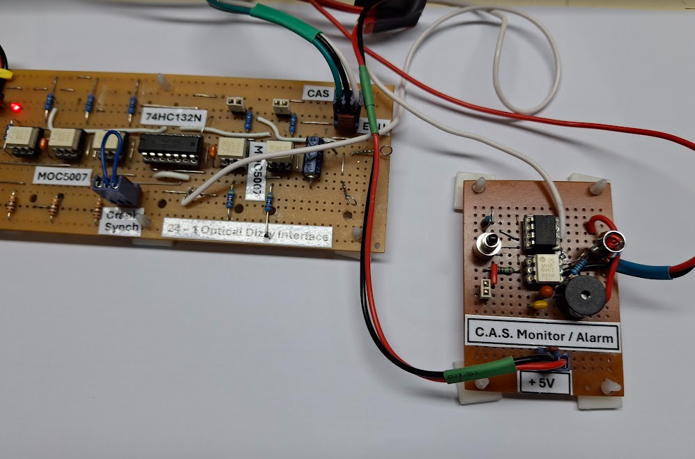
Well almost a couple of weeks later, & I'm still shocked, that the C.A.S. is only used for starting the engine, & plays no part thereafter, until You next restart the engine. I've researched it, & asked Google A.I., and it is true ! Apparently some modern ECUs in production cars, behave the same way. The theory behind it is, that 2 off revolutions of the crankshaft, is too long to wait, to get a new C.A.S., as in two revolutions, the engine could have accelerated or de-accelerated, considerably. The literature on the net; keeps saying things like, "guessing where the next C.A.S. will be". "Guessing " ? I thought the whole idea of the C.A.S. was, that you had a "rock solid" timing marker, pre T.D.C. No: 1 cylinder, so that the next four, six, or eight ignition triggers & injection signals would be spot on. So everyone keeps mentioning , about timing irregularities due to the camshaft drive wear in sprockets & chains, & belt stretch & whip, on OHV engines, & after starting, the C.A.S. never gets used again. So why did I go to the trouble to get rid of those issues by logically creating a C.P.S. / C.K.S. (crank position signal), when it is only used to start the engine. Apparently, in most modern cars' ECUs; once you start the engine, using the C.A.S., you can drive the car all day, & never use it again. I proved that on the bench, but researching the net, & asking A.I. confirms it is completely true, for a lot of vehicles. So after this enlightenment, the next question is; why does the driver not know ? I'm presuming that in many modern production ECUs, there is an error code is sent back to the system. Sorry, but I want to know straight away, so I don't get stranded on the middle of the Hay Plains, because I stopped for 5 minutes, to takes some photos; only to find when I got back into the car, that the engine won't start. So I've been attempting to build a little auxiliary circuit, that is independent from the ECU; that can detect a missing C.A.S. signal, & alert the driver. There is a bit of timing involved, & I finished up using a tiny Picaxe 8 pin microprocessor, to do all the work. I only needed a total of three inputs/outputs. (2 x inputs, 1 x output) 1. C.A.S signal In. 2. Alarm output. 3. Acknowledge & Reset Alarm. I've refined the code over a few days of testing, & it works extremely well. When You apply power to the ECU, when you first start the car, You don't want the thing alarming, so when the ignition turns on, the alarm system stays quiet for 20 seconds, & does no detection; by which time the engine should have started, & be idling. The program works by creating a window "timewise" , after the current C.A.S. pulse, when it expects the next pulse to arrive. There is about a + 40% margin in the length of this window, as the engine may have accelerated during the next 2 off revolutions. If the pulse does not appear, or get detected, during that next time window, the alarm is activated. The calculations of the window for detection, cover the rev range of 700 RPM, right up to 7000 RPM. The alarm is in the form of a flashing L.E.D. & a small piezo electric buzzer. In addition to that; you want to know that the alarm system is working, so the buzzer gives a little blimp, & LED flashes every 8 seconds. I call it a "heartbeat" signal. You can turn of the buzzer off, & just have the L.E.D. flash once every 8 seconds. I've tested it for a couple of days, & it works perfectly, on the bench. So we live & learn, but I'm not "out on a limb", as if & when either my C.A.S. or C.P.S./C.K.S. pulses fails, I actually have two fitted to the engine. I have the C.A.S. single pulse generated by the distributor at camshaft speed. If the C.P.S. (crankshaft position sensor) fails I just use the C.A.S. from the dissy, without the logically "ANDing" with the C.P.S. If the dissy C.A.S. pulse dies, then I simply place the engine in "wasted spark" format, & the engine will start, using the C.P.S. pulse only. So I'm not going to get stuck in the middle of the Hay Plains. I'm just wondering whether any modern ECUs, can automatically or manually can switch to wasted spark, if the C.A.S. fails. Have to ask Google A.I. that; & see what it can find out. Cheers Banjo.
-
Late yesterday, I built a new interface board between the optical distributor, with a 24 - 1 punched tooth S.S. disk. I changed the inversion of signals around, which saved the use of one (1) off 14 pin logic integrated circuit. This particular board incorporates the use of a single C.P.S./ C.K.S.(crankshaft position sensor) to logically AND with the single C.A.S. pulse produced by the distributor, to produce a single stable C.A.S. pulse per every two crankshaft revolutions. I had it all hooked up this morning & working with the Speeduino, pushing out trigger pulses reliably. I then unplugged the Hall Effect sensor, that was producing the combination C.A.S. pulse; expecting the Speeduino to stop producing trigger pulses. IT DID NOT ! It continued to pump out trigger pulses, without any C.A.S. pulse at all. I then turned the Speeduino off; restarted it, without the C.A.S. pulse, & nothing happened at all. (no trigger pulses) I'm sitting there for several minutes scratching my head, as I had never thought about this previously. How could this be. So I Googled it, & there was a lot about it. Apparently, it is a flaw in the original design of the Speeduino, that was left there, because of a safety concern. Apparently; once Speeduino gets a signal from the C.A.S. sensor, it can do without it, as it can produce a count of the pulses around the perimeter of the crank or camshaft disk/wheel/etc. to know where the C.A.S. pulse should be. So the reality is; that if You start the engine OK, & drive all day; but during the day, the C.A.S. signal drops out, due to faulty / broken cable, or a crook Hall Effect sensor; the engine never stops. However, when You come out of the motel next morning, to continue your journey; the engine will not start. I was flabbergasted ! The logic is, that You don't want the engine to cut out as You carry out a RH turn, across oncoming traffic, because of a faulty connection, on your C.A.S. pickup sensor. I see the logic of that; but the driver is totally unaware of the fault, until He/She goes to next start the car. So I do some research, & find there is a "fault signal" (lack of C.A.S) out of the micro, which you'd then have to wire out, & hook up. Apparently, TunerStudio has a little light that comes on, if there is no synch; but we don't drive around with TunerStudio running on our laptop, on top of the dash. So this afternoon, has been spent researching how I can build a circuit, quite independently of Speeduino; that can detect the loss of one or more C.A.S. pulses, & bring up a warning light & maybe audible sound; to warn the driver that the C.A.S. pulse has been lost. I'll have to do some research & see if this happens with other brands of ECU. I did research read in passing; that some early model Megasquirt models, behaved similarly. We live & Learn ! Cheers Banjo
-
The most likely part of the ECU over system; where noise can be "induced", into the system, is at the COPs, themselves; right at the top of the engine. C.O.P.s commonly have a common return line to chassis ground, which serves both the +12V supply that charges the primary of the C.O.P. ignition coil, & the return line for the +5V trigger pulses. There seemed to be little I could do in this area, as it was widely acknowledged on the net, that it is a major source of trigger signal degradation. It was then, I discovered that there are C.O.P.s that have a separate return line for the +5V trigger pulses. They are used on late model V6 Commodore & GMH vehicles. I purchased a new one on line, & it does work admirably. It is an ICON brand with P/N IGC-277M. This provided the ability to separate the +12V supply return, & the +5V trigger pulse return line. However, I did notice, when I placed a multimeter between these two returns, that it was not an open circuit. There was a resistance between them, of exactly 10K ohms. Puzzled over this, & then asked Gogle A.I. Why is there a 10K ohm resistance between the two +12V & +5V trigger signal, return lines, on an ICON model IGC-277M C.O.P. ignition coil, when I was led to believe they were completely separate from each other. Here is A.I.s Answer: The 10K ohm resistance you're measuring between the +12V power supply and the +5V trigger return (ground) lines on your ICON IGC-277M ignition coil is a standard feature of its internal "Smart Coil" architecture. While these lines appear "separate" in a wiring diagram, they are internally linked for circuit protection and signal stability: Internal Pull-Down Resistor: The IGC-277M uses a 10K ohm pull-down resistor to ensure the trigger signal remains at a solid 0V (ground) when not actively being fired by the ECU. This prevents electromagnetic interference (EMI) from causing "ghost" sparks. Integrated Igniter (Smart Coil): Because them IGC-277M is a Coil-on-Plug (C.O.P.) unit with a built-in power transistor, it requires a shared reference point to switch the high-current 12V primary based on the low-current 5V trigger. The 10K resistance is the path your multimeter sees through the internal switching circuitry. Protection against Back-EMF: This high-resistance path protects the delicate 5V ECU driver from the massive 12V inductive spikes (back-EMF) generated when the coil's primary field collapses. Open Circuit Detection: Many modern ECUs use this specific resistance to monitor the "health" of the coil. If the ECU sees an "open" (infinite resistance) or a short, it can trigger a misfire code (e.g., P0351–P0356). Note: If you measure significantly less than 10K (e.g., <100 ohms), the internal igniter is likely shorted. If you see infinite resistance, the internal trigger circuit is "open" and the coil will not fire. __________________________________________________________________________________________ However My 4 off +5V trigger signals leave the shielded 4 off twisted pair cable & enter the final module via 4 off opto-couplers, so there is no signal or ground return line. I then decided to produce a +5V power supply for providing the 4 off P Type MOSFETs to provide the power to the trigger inputs on the C.O.P.s. You can obtain little 12V DC to 5V DC isolation module, where there is no connection at all between the ground of the ingoing 12V supply; & the ground of the outgoing 5V supply. Then I discovered, that the +5V output was not regulated. After a lot of research & experimentation, I decided to obtain a 12V to 9V isolator module, then feed the 9V into the input of a precision LM2940 +5V regulator, which will supply the P type MOSFET switches (TC4424). The +5V trigger pulses are not "hungry", in terms of power/DC current required, so the TC4424 P Type MOSFETs are fine, & are what are fitted to the Speeduino ECU. So that is it, basically, & it is all working on the bench perfectly, with a 4K head & four spark plugs. Just need to tidy it up a little bit, before I connect & install in on the 5K engine. Cheers Banjo
-
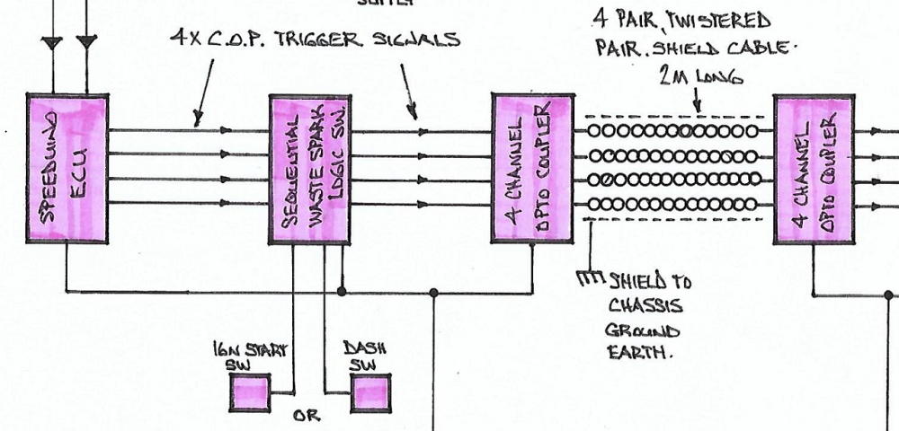
The next part of my extra modules & modifications, after the ignition signals have been produced by the ECU; were processed to be either in waste spark, or sequential format; was to address the area where the four C.O.P. trigger signals, leave the "safe confines", of a shielded metal ECU case, & head out across 1 - 2 meters of space in the engine compartment; to the C.O.P.s on the top of the engine. Four (4) little 5V pulses, just 3-4 m/sec wide, in a "hostile" environment, that is full of electrical noise, that can be picked up, & which results in distorting the shape & timing of these critical C.O.P. trigger pulses. The wiring of these C.O.P. trigger signals could simply be carried out, by placing the signals in a shielded cable, where the "shield" in connected at the ECU end only, to a good chassis ground. I decided to go two steps further. One was to isolate the four signals completely from each other, by placing eight (8) opto-couplers; one at each end of each trigger line. In addition to that the four pairs of wires in the cable are twisted pairs. That allows any induced signal into one wire would also be induced into it's return path, & they would cancel the noise out. This virtually makes the path across the noise hostile path to the COPs; noise free, & results is the four signals arriving at the C.O.P.s as good, or better, than when they left the ECU. They should/could be better; as all eight (8) opto-couplers have hysteresis switching built in, which results in their rise & fall lines, being extremely sharp. (very important) as the rising edge, in particular, carries the timing information to each C.O.P. Next time, I'll describe the final block, to provide the power required to these four (4) =5V trigger pulses with P type MOSFETS, right at the head of the engine. I have been concerned, that a few of my techniques may be a bit over the top, & too far fetched. I sent a longish enquiry to the Google A.I. site, & asked what it thought of my design. It advised that everything I'd done, including the high speed logic I.C.s would provide the system, (end to end) the very best chance of being almost totally "noise free" Cheers Banjo
-
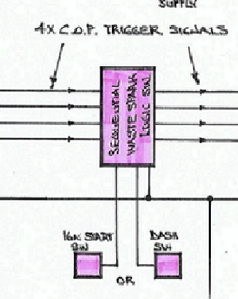
The Sequential / Wasted Spark logic switch, took a little longer to produce. The idea was simple; but the turning it into hardware, took a few tries, to get it right. The brief to myself was to take the four (4) off ignition pulses from the Speeduino; & then produce the same four pulses, in the correct firing order; in either sequential or wasted spark mode. Sequential, has been; & still is, the preferred way of operating the ignition system in modern vehicle engines; primarily as emission standards in most developed countries stipulate that. However, in theory, wasted spark operation, particularly when starting & cranking the car; should find C.A.S. pulse synch earlier, & therefore start the engine more quickly. A search on the web, using A.I. found that a number of modern car manufacturers do; exactly what I was theorizing; by starting the car in wasted spark mode, then switching to sequential, once it is running. It's hidden deep inside these vehicles ECUs, & no one would even suspect that is happening, every time the engine is started. The starting was very simple, as when You turn the ignition switch on, you twist it that little bit further to place the switch in the “start” position. I simply picked up this signal which normally drives the starter motor starting relay, & fed that to the “Switching Logic Module”, via an Opto-coupler. (12V signal in, & 5V logic signal out.) As soon as the engine starts, & you release the ignition switch start position, the logic switch automatically reverts back to sequential ignition mode. However, I also wanted for my own interest; a switch on the dash, so I could switch the engine ignition mode from Sequential to Wasted Spark mode; so I could see if I could detect any improvement in particular driving conditions & engine loads. Again, this dash switch would be electrically isolated from the 12V system, via an opto-coupler. There was also an “OR” function built in, so that the Sequential to Wasted Spark mode switch would take place, from both a start switch “or” a dash switch. I started out using "fixed logic" for this switch; changed to a single processor integrated circuit, requiring programming; but eventually simplified the hard logic model, with some very fast logic chips. The outputs of this module, already now had the firing order required built in. It is simple then to attach the four (4) C.O.P. trigger signals, to the right C.O.P. Simply; 1 to 1; 2 to 2; 3 to 3; & 4 to 4. The circuit appoints the correct sequencing. Cheers Banjo
-
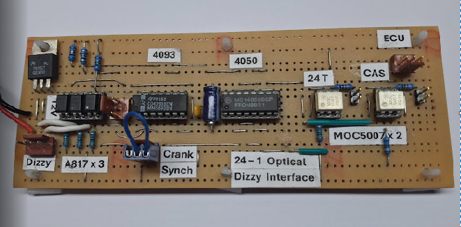
I want to describe each block in yesterdays sketch, so You can understand the logic, of why I have headed this way. In truth, You don't really need any of this additional electronics. The four ignition outputs from the Speeduino will drive the four (4) COPs without too many issues. However the Speeduino ECU, just produces four (4) pulses in a row, & has no particular firing order, built into the sequence of those four pulses. It is up to the installer to connect the four (4) ignition outputs, 1,2,3 & 4, to the appropriate ignition coil or C.O.P., based on the firing order; which in our case is 1 - 3 - 4 - 2. In other words . . . Speeduino Ignition O/P#1 to C.O.P. 1 Speeduino Ignition O/P#2 to C.O.P. 3 Speeduino Ignition O/P#3 to C.O.P. 4 Speeduino Ignition O/P#4 to C.O.P. 2 The distributor is where this all starts; as it provides a string of evenly spaced pulses per revolution, which is actually equal to two revolutions of the crankshaft. A distributor with a 24 pulse output, is equivalent to a crank mounted trigger wheel with just 12 off teeth or magnets etc. They both produce 24 pulses per 720 degrees rotation of the crankshaft. I settled for the distributor to produce the trigger pulses, as it the easiest way for anyone get started, with this exercise. Take an olde Bosch produced K series distributor body, & gut it, & fit an optical punched disk assembly from a Nissan, Daewoo, or Mitsubishi engine, & you are away & running quite quickly. The added benefit for me, was if while I'm road testing this system, & it breaks down, or it just stops: I can very quickly revert to an original dizzy, & get back home. However, by using a cam driven dizzy, we are introducing the "wavering" of the C.A.S. (Cam Angle Signal/Sensor), as a result of the "slop" & "wear", in timing chain; sprockets & helical gears; & belt flex/stretch in twin OHV engines. Earlier in this thread I described the first block in yesterday's block diagram; labelled the "Distributor Processing Interface". Basically, it logically produces a C.A.S. pulse when a single pulse from the crankshaft, coincides with the wider C.A.S. distributor pulse, once every two revolutions of the crankshaft. The two outputs of this "Distributor Processing Interface", are then feed into two (2) opto couplers, which are a device that uses a infra-red light source inside the MOC-5007; such that the input terminals & the output terminals are completely electrically isolated (no common ground circuit). In addition, the MOC-5007 opto-coupler has hysteresis built into it's switching, which guarantees a very sharp clean transmission between the On & Off parts of the signal. ((basically, is switches on, at a slightly higher threshold voltage, than the voltage at which it switches off. eg: On a 0-5V signal it might say switch on a 4V; but not switch off, until the signal gets down to say 2v. This leaves a 2V dead-band in the middle of the switching band. I've made full use of opto-couplers at several places in this circuit, & oscilloscope checks of the final +5V pulses, arriving at the trigger inputs of the four (4) off working C.O.P.s; indicate very clean & sharp pulses. These resultant pulses are fed into the RPM1 & RPM2 pulse inputs on the Speeduino ECU, which certainly won't need the assistance of any VR Conditioner; to produce clean sharp pulse to the micro-processor. ( Oh, I hate those VR sensors) This Distributor Processing Interface actually has a total of 5 off Opto-Couplers on board. Three (3) off isolate the pulses coming into the board from the trigger pulse & CAS pulse from the dizzy, whilst the third isolates the single C.A.S. pulse from the crankshaft pulley. Tomorrow; I'll describe the Sequential/Waste Spark switch block, & opto-coupler stage, before the four (4) C.O.P. trigger signals are sent on their merry way, out into the engine bay; on-route to the four (4) C.O.Ps (Coil On Plug) mounted on the engine. Cheers Banjo
-
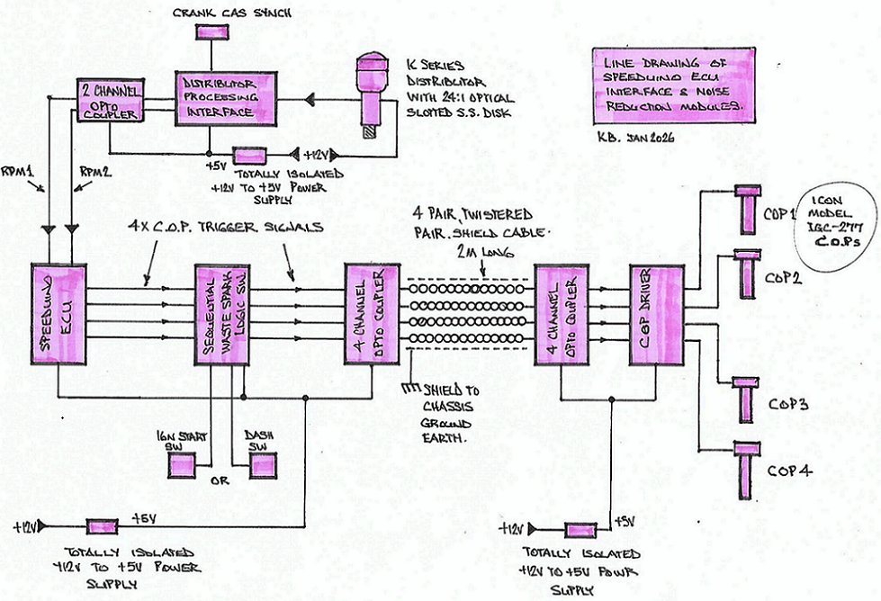
Been a few weeks, since I introduced the "switching on the fly"; & on cranking, of the Speeduino ECU ignition outputs from "Sequential' to "Wasted Spark"; & visa versa. I then pointed my attention & efforts to another area of ECU operation, that has been of great interest to me; & that is regarding "noise"; & how it can cause havoc in ECUs, operating in a very "electrically noisy environment. In the real stationary world, we have our feet standing on the earth, & electrical noise can be directed to ground. In a vehicle, with rubber tyres, that is not possible; although You will be aware of the straps that rub on the roadway, under the car, & remove static charges in the vehicle frame, which are apparently are a source of dizziness & motion sickness etc. Apart from the early car radios, that were prone to picking up noise from the cars engine operation, there was not much else that was affected. The ignition systems were mostly 12 volts, & any inference could be eliminated by a capacitor fitted to the offending electrical device. Then along came electronic controls, in their droves; to both engine & general lighting, & A/C controls. The problem with modern electricals, when fitted to automobiles; is that they rarely are powered by +12 volts. +5V is common, & microprocessors in ECUs, can often operate of DC voltages, as low as 3.3 volts DC. To some extent; the ECU itself, can be mounted in a metal enclosure or box, & suitably earthed to the chassis frame, to protect it from "radiated noise" that passes through the air, like a radio wave. However, once wiring to & from sensors & actuators in the engine bay are wired back to the ECU, then the noise is introduced to the ECU, via this cabling. Now it is possible to wire up every sensor & actuator attached to the ECU, via "shielded" cable, & the shield connected to the chassis ground; & this will obviously assist. However, the chassis ground or zero volts is not the earth. It is an artificial floating ground plane. So here we have a ground frame in the car carrying enormous currents (100s of amps) during say "cranking the engine" on a cold morning; along with tiny / minute currents from sensors & the likes, that ECU needs to read accurately, to base it's controls upon. The starter motor commutator & brushes are one issue, known to us all; but there is another one, much more intrusive. "Spark Plug discharges". Unlike the starter motor, that is only used during starting the car; (remember how olde cars used to turn the radio off, (whilst the ignition switch was in the start position) the spark plugs are constantly creating arcs & electrical airborne noise, whilst ever the engine is running. Luckily, the actual spark occurs inside the engine, which creates a "protection metal shroud" from the actual arc itself. However, the coil or C.O.P. that produces that 20-30Kv spark, is out in open air. Anyone who has opened the bonnet, on a dark night; of an olde engine, running a dissy cap with HT leads across to the spark plugs, would be well aware of the coronas, visible across leads & H,T, carrying devices. So we move on, & the advent of the C.O.P.; & now we have a coil primary & secondary winding, along with a +5V DC trigger signal, sharing a common ground connection. I'm really surprised, that C.O.P.s work as well as they do. I was however, pleased to find, I'd been "hiding under a rock"; & that there are now C.O.P.s with a separate 5V return wire; to the chassis ground, for charging the primary of the H.T. coil inside the C.O.P. The one I have recently purchased, is an ICON, model IGC-277M. There are several ways we can resolve this problem of electrical noise being induced into the 12V system. Most ECUs, & their sensors, are powered by +5V; but share the ground with the 12V system. Enter the fully isolated DC to DC power supply, with a + 12V input, & a +5V output, but completely electrically isolated ground circuits. I've gone a bit overboard, by adding three off these to my Speeduino system, as depicted in the hand sketch below. Next post, I'll describe how I have used opto-couplers, to totally isolate one part of the system, from another; as well as using totally "shielded" twisted 4 pair cable, across that electrically noisy/hazardous path/journey from the ECU on the fire wall, or under the dash; to the four (4) C.O.Ps. on the engine itself. I've actually used a total 13 off opto-couplers in the circuit, plus 2 off for the signals from the ignition starter switch & dash switch, to change the spark control from sequential to waste spark, on the fly. Any questions or queries, please add to this post. Cheers Banjo
-
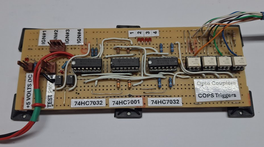
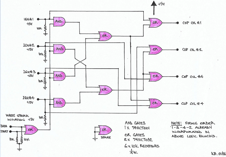
Update on the logic to switch ignition (& injection) on the fly. The Picaxe 14M2 programable microprocessor needs interrupt inputs for the four (4) trigger pulses, from the Speeduino ECU. Unfortunately, I found the 14M2 only has three (3) interrupt inputs. I upgraded to the 18M2+ Picaxe 18 pin micro, which has seven (7) off interrupt inputs. It worked well, but there were minute time differences between the time the pulses entered the micro, & when they left. This would not be discernible at low speed revolutions; but could induce small changes to the timing, at higher RPM. For that reason, I returned to the fixed logic I first started out with, but refined it; & utilised high grade CMOS HC logic integrated circuits, with hysteresis built in. The hysteresis produces very sharp edges on the output pulses produced, which reduces chances of any noise issues. The "AND" gate IC I used was a 74HC7001 (4 x AND gates), along with two off model 74HC7032 (4 x OR gates). The full circuit is depicted below, for anyone that wants to build it themselves. It worked out nicely, using all but one "OR" logic element in one of the "OR" ICs. Note that the common firing order for a 4 cylinder engine of 1 - 3 - 4 - 2 has already been incorporated in the design. The Speeduino ECU for which I am using this, does not have provision for allocating or programming the firing order. It simply outputs 4 off ignition pulses, in succession. It is up to the installer, to wire the four (4) ignition outputs to the correct cylinder. Any questions, just give me a yell. If You are questioning whether there is any point, or good reason, for adding this wasted spark/sequential switch; consider what A.I. had to advise about it, when I questioned it. Question to A.I. Are there any advantages in cranking / starting an automobile ICE engine in waste spark mode, & then automatically switching to sequential, once the engine has stated ? Yes, starting an internal combustion engine (ICE) in waste spark mode before automatically switching to sequential mode is a common strategy used by many modern Electronic Control Units (ECUs) Advantages for Starting Faster Synchronization: Wasted spark mode only requires a signal from the crankshaft to begin firing. Sequential mode requires identifying whether a cylinder is on its compression or exhaust stroke, which usually necessitates waiting for a full camshaft revolution. Firing in waste spark mode allows the engine to start as soon as the crank sensor is synced, rather than waiting for the cam sensor. Improved Starting Reliability: Firing twice per cycle (on both the compression and exhaust strokes) increases the likelihood of ignition during the first few rotations when air/fuel mixtures may not be perfectly homogenous. Fail-Safe "Limp Home" Mode: If a camshaft position sensor fails during operation or at startup, the engine can regress to waste spark mode to remain functional. Spark Plug Cleaning: The "wasted" spark during the exhaust stroke can help clean the spark plug by burning off any leftover fuel or oil vapor, which is particularly useful during cold starts. Benefits of Switching to Sequential Once the engine has started and the ECU has confirmed the camshaft position, switching to sequential ignition offers several advantages for long-term operation: Increased Coil Lifespan: Sequential mode fires each coil half as often as waste spark mode, reducing heat buildup and extending the life of the coils. Better High-RPM Performance: Because coils fire less frequently, they have longer dwell times (charge times) between events. This is critical for high-boost or high-RPM engines where maintaining a powerful spark is necessary to prevent "spark blowout". Precise Individual Cylinder Tuning: Sequential ignition allows the ECU to trim ignition timing for each individual cylinder, leading to smoother idling and better overall engine efficiency. Reduced Emissions: Eliminating the extra spark in the exhaust stroke and optimizing timing per cylinder helps reduce emissions, which is why most modern OEMs use sequential systems for standard operation. I liked the point in A.I.'s response, regarding limp mode, if you lose a C.A.S pulse, resulting in the engine stopping. I could detect C.A.S. failure & automatically switch to Wasted Spark, & bring up a warning light on the dash ? I'm tempted; bt must get this project "on the road". _______________________________________________________________________________________________ As a result of A.I.s answer to my previous question, I then asked A.I. the following question. What auto manufacturers have included an ecu feature for their engines, where the ignition, & injection (if applicable); start the engine is waste spark mode, & then switch to sequential operation, once the engine is running ? Question 2: Do any of these ECUs have a feature, where if the C.A.S. (camshaft angle sensor) fails, whilst driving; that the engine automatically switches to waste spark, & a warning light, or error message is produced by the ECU ? Many modern automotive manufacturers and aftermarket ECU providers utilize specific startup and fail-safe logic involving wasted spark and sequential operation. 1. Manufacturers with Wasted Spark to Sequential Start Logic Several manufacturers use a strategy where the engine initially fires in "wasted spark" mode (firing every 360° of crankshaft rotation) until the Camshaft Position Sensor (CAS) provides a sync signal, at which point it switches to full sequential operation (firing every 720°). General Motors (GM): Many LS-series engines and older Delco-based systems (like those in Buick and Chevrolet) use this logic. They initially fire in a "batch" or wasted mode to ensure a quick start and then transition to sequential once the cam phase is identified. Nissan: Various RB and SR series engines with factory ECUs are known to use a "limp-to-start" wasted spark logic if the cam signal is not immediately clear. Ford: Older EEC-V systems and some modern "dumb coil" applications (like certain Coyote Mustangs) can operate in wasted spark or sequential depending on the trigger setup. Aftermarket Manufacturers: Many high-end aftermarket ECUs explicitly include this feature to improve starting speed: Haltech (Elite/Nexus series): Allows for wasted spark startup and automatic transition to sequential. Link ECU (G4+ and newer): Can be configured to start in wasted spark and switch to sequential once the cam sync is achieved. 2. CAS Failure & Fail-Safe Modes Most modern ECUs include "fail-safe" or "limp home" logic to handle a Camshaft Angle Sensor failure while driving. Automatic Switch to Wasted Spark: If the CAS fails while the engine is running, many ECUs (such as Link ECU and Bosch-based factory units) will continue running by switching from sequential to wasted spark ignition. Since the crankshaft sensor still provides engine speed and TDC information, the engine can maintain operation, though with less precision. Warning Indicators: Check Engine Light (MIL): A CAS failure will almost universally trigger a "Check Engine" light or an error code (e.g., P0340). Limp Mode: The ECU may limit RPM or boost (in turbocharged cars) to protect the engine, as it can no longer accurately monitor individual cylinder timing or variable valve timing (VVT). Start-Up Behavior after Failure: If the CAS fails before starting, many systems will not start at all because they cannot determine the initial firing order. However, some systems are programmed to "guess" the phase or attempt a wasted-spark start by trying both phases until the engine fires. Cheers Banjo
-
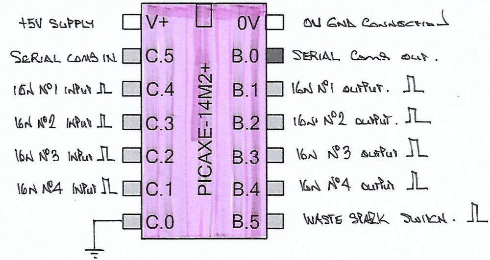
On pages 6 & 7 of this thread, I noted my interest in providing a switching mechanism, to my system; that allowed it to be switched between Sequential & "Wasted Spark" mode during the starting procedure. Starting an engine in sequential, can take up to 2 revolutions of the crankshaft, before the ECU receives a CAS pulse. I would also like to be able to manually switch the engine firing (& injection) mode, to "Waste Spark" manually; whilst driving under different conditions; to see if I can discern, any difference in performance; under different real road load conditions. I was able to produce the logic to achieve this, using 5 off dedicated logic ICs, as depicted in an earlier post. Works perfectly, but unhappy, that I need "real-estate" on my printed circuit board for 5 off dedicated integrated circuits (ICs). As the logic itself, is pretty simple; I was interested to see if I could program the logic, into a small dedicated programable microprocessor. It was successful; & I used each & every pin on a 14 pin Picaxe 14M2 micro, which are commonly used for education purposes. However, they can be run at up to 32MHz, so are no slouches. They are only a few dollars each, & can be programmed in a free editor program, using "basic" commands. In fact; the program only required eleven (11) lines of code. As I stated earlier in this thread; the Speeduino setup does not provide for setting up a firing order, in TunerStudio. It has 4 off ignition outputs, & four of Injector outputs, which simply fire in order from the board, as 1,2,3,4 . It is up to the person, wiring up the system, to connect the 4 off ignition outputs to the correct cylinder coil &/or injector. In a "K" series engine. Ignition No: 1 Output to cylinder No: 1 Ignition No: 2 Output to cylinder No:3 Ignition No: 3 Output to cylinder No: 4 Ignition No: 4 Output to cylinder No: 2 I was able to include this firing sequence, into the code, so that whilst installing the system, the firing order is imbedded. Ignition No: 1 Output to cylinder No: 1 input Ignition No: 2 Output to cylinder No:2 input Ignition No: 3 Output to cylinder No: 3 input Ignition No: 4 Output to cylinder No: 4 input The other concerns I had, was ground/chassis/earth noise, particularly for the +5V pulses required by the DENSO COPs. Although the DENSO COPs, are a 4 wire connection, there is only a single wire "trigger" input for the +5V pulse. The return line is shared with the ground/chassis connection, for the +12V supply, for the COP. The single chassis ground connection, also handles the large coil primary charging current. I can & am using a tiny opto coupler (model A817) to fully isolate the output of my control system, from the DENSO coil. However, the fact remains, that the COP primary coil & 5V trigger signal, both share a common ground. I have thought about using a "fully isolated" DC to DC converter, to produce the +5V voltage ? There are ignition coils manufactured in the world to the IGN-1A standard, which provide 5 pin connection, with a separate ground connection, for the +5V signal return; to overcome this problem I mentioned above. However, my searching, as yet; has not found one in a COP format. Common 5-Pin Wiring Configuration For coils like the IGN-1A, the 5-pin connector typically follows this noise-prevention logic: High-current Battery Ground (Ignition Power Ground). Low-current Signal Ground (Reference return to ECU). Battery Positive (+12V Power). Trigger Signal (5V or 12V pulse from ECU). High-current Battery Ground (Secondary/Chassis Ground). I happen to like the DENSO COPs, as all my other Toyota vehicles use them (Corolla/Yaris/Echo/Camry) If anyone is interested in replicating, what I've done, then drop me a PM, & I'll provide you with the code. I can also code PICAXE 14M2 for You, & forward that, for the cost of the micro. Any questions or concerns; please give me a yell. Cheers Banjo
-
Hi Jasper, I've never used one; so cannot personally advise good or bad results. In this case, I turned to Google A.I., which scans all available information on the internet, to make it's conclusions, or suggestions.
-
We are starting to show our age, when we get into that era ! I guess you've read this following history, at one stage. https://www.secret-classics.com/en/drive-toyota-celica-ta22-st/ Others may like to. True story ! I was working on contract in PNG, in the highlands. I had a girlfriend, who had bought an imported RA40 hatchback, in that deep bronzy brown colour. It was Her pride & joy ! Just like this one pictured. Note: I did however, love the later series of this model, which featured a "Mustang" like rear tail area. https://carbuzz.com/toyota-ford-mustang-copycat/ She returned to Cairns, where She was living. When it was time to "go finish"; I flew to Cairns, where She was waiting at the airport. She had her bags packed, & the very next morning, we drove Her RA40 down to Brisbane, & later to Sydney, where we married. Yes, we drove away from the wedding reception, in the RA40. In subsequent years, we drove it all over Australia. One trip was a two (2) day dash from Adelaide to Sydney, overnighting in Broken Hill. It loved the wide open spaces, & with a 5 speed gearbox, never felt like it was at it's limit. Never let us down. I think there was once on a trip along the Murray, it was playing up; & I diagnosed it as a fuel pump issue. Hobbled into the local Toyota agent at Mildura, or somewhere; & they had a repair kit. Drove to a park, & fixed the fuel pump, on the side of the road. There were; (& are still) a very reliable vehicle. The hatchback was great ! You could lie the back seats down, & the "boot" area, plus back seat You could actually sleep in, unless You were over 6 foot tall. Cheers Banjo

-
Cheers Banjo
-
I asked Google A.I. the following questions.
-
Hi Jasper, Seems like You have checked everything, but the car being quite olde, there are a number of issues. If You go look on the internet, it does turn up a few possibilities, for your Daihatsu. ____________________________________________________________________________________________________________________________________________________________ If a 1982 Daihatsu Charmant LE fails to idle properly after all standard manual tests have been performed, the issue typically stems from specific aging components or internal carburetor failures that are not easily detectable through standard diagnostic routines. Hidden Carburetor and Fuel Issues Because the 1982 Charmant uses a carbureted system, standard tests may miss internal mechanical wear: Clogged Internal Idle Circuits: The fuel path for the idle circuit is highly convoluted, often traveling above the fuel level in the float bowl before descending. If the car has sat with old fuel, these internal passages can clog in ways that surface cleaning or "blowing through" cannot fix. Worn Needle Valve Tip: Microscopic wear on the needle valve tip can allow fuel to leak past into the engine, causing a rich mixture that cannot be corrected by the idle mixture screw. Malfunctioning Economizer Valve: If the idle is too rich and cannot be leaned out via adjustment, the economizer valve may be feeding fuel into the engine incorrectly. Sticking Automatic Choke: On older carbureted engines, a choke that is even slightly sticking or misadjusted will disrupt the air-fuel ratio enough to prevent a steady idle. Vacuum and Air Leaks Standard manual checks often focus on visible hoses, but hidden leaks can be more subtle: Carburetor Base Leak: Vacuum may be leaking around the base of the carburetor or through worn-out gaskets rather than the hoses themselves. Intake Manifold Gasket: Worn or damaged gaskets can cause a vacuum leak directly at the engine block, which is difficult to see without specialized testing like a smoke test. Clogged EGR Valve: Carbon buildup inside the EGR valve or its passages can cause stalling at idle. Mechanical and Ignition Timing Ignition Timing "Out of Whack": Even if set to manual specs, wear in the distributor or on-board computer components can cause timing to drift, resulting in a poor idle. Worn Valve Seals or Piston Rings: In older Daihatsu models, worn internal engine components can lead to reduced performance and erratic idling that external adjustments cannot fix. ____________________________________________________________________________________________________________________________________________________________ Hope somewhere in amongst that, You spot something, You've not checked as yet. Having had a couple of 4K engines, the Intake manifold gasket leaking, is quite a common issue. I'd be taking off both inlet & exhaust manifold together, & then run a straight edge across them. As it's been happening for some time; You may even see evidence of the leak, with discoloration of the metal surfaces, each side of the gasket. Let us know, if any of these suggestions, bring your idling issues to a sucessfull resolution. Here is a post on this forum, written 15 years ago, where the issue, I'm suggesting was discussed. https://www.rollaclub.com/board/topic/38875-4k-intakeexhaust-gasket/ Cheers Banjo
-
Hi Gino, Welcome aboard ! Many members on RollaClub run aftermarket ECUs, of various types; but You are the only person, who has advised they are running a Speeduino; & a V0.4 at that. I haven't actually got any road miles under my belt as yet, with my Speeduino. All my experimenting, with various trigger systems, has been on the bench. My Speeduino, will be running my 5K initially, which is a running working test engine, on a stand in my garage. That will be to prove the synchronizing of overlapping CAS signal, with the crankshaft single pulse per revolution. I've had it running on the 5K a while back, & then it was off to bench, for lots of triggering experimentation. Then it will transferred to my KE-30 2 door sedan. As I won't then have a test Speeduino, on the bench, to further experiment with; I've recently finished a Speeduino V0.4.3d. It is a nice ECU, as it's board is 30% smaller than my V0.3.7 Speeduino. The V0.4.3d has Bluetooth & idle control, so looking forward to that. This is what it looks like now, as this week I hooked up a 40 screw down block, so that all 40 pins on the Speeduino V0.4.3d, can easily be hooked up. Interested to know what type of triggering system you used, & how You implemented it. Post some pics of your setup in the your car, with some details of the setup, including ignition coils or COPs etc. I'm presuming that it is currently controlling "ignition only" ? I've actually got a second test engine in my garage, which is a 4K with a 7KE fuel injection setup. That will be the final step, so a lot more fun, & learning, before I get to that point. Cheers Banjo
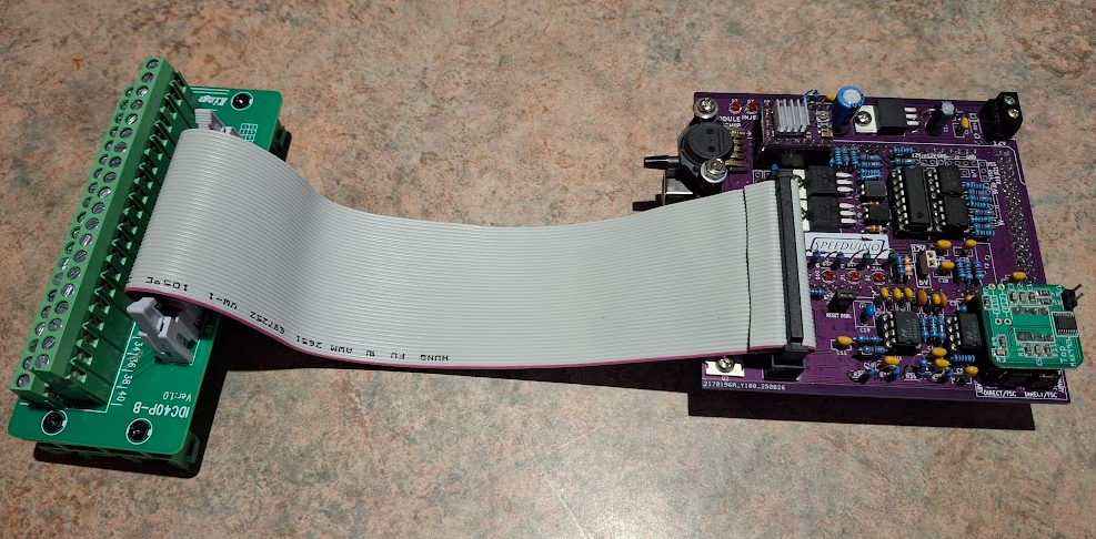
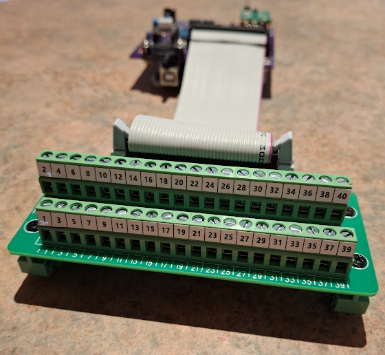
-
Further to my post yesterday, I should warn, that what I'm doing, may not work for everyone, as trigger signals to various industry COPs, can vary in voltage & polarity. The COPs I am using are Denso 4 wire COPs, widely used in current & recent Toyota model Corollas, Yaris & Echo vehicles. The fourth wire I am not utilising; as it is a feedback signal to the Toyota factory ECU, to indicate whether a COP has fired correctly or not. Most COPs, are triggered by a +5v pulse from the ECU. However, there are COPs that apparently use a 0V pulse. There are apparently; also COPs, in the world that use a +12V signal. I discovered this by doing a bit of research last night, on Google AI. Here is what I asked, & how Google A.I. replied. Do all COP (Coil Over Plug) automotive ignition coils trigger off a +5V DC signal being applied to them, by the ECU; or do some brands use a negative going pulse, to trigger them ? No, not all Coil-On-Plug (COP) ignition coils trigger off a positive 5V DC signal . While a 5V positive pulse is common, other triggering mechanisms exist across different vehicle makes and models. The specific triggering signal depends on the coil's design and how the ignition amplifier (ignitor) is integrated into the system: Integrated Ignitor (3 or 4-wire coils): The majority of modern 3-wire and 4-wire COP systems have the ignition amplifier built directly into the coil assembly. These typically receive a low-voltage 5V trigger pulse (usually positive-going) from the Engine Control Unit (ECU). The coil fires when internal electronics are signaled by this voltage pulse. External Ignitor (2-wire coils): In older or different systems using 2-wire coils, the switching (triggering) is done by an external ignition amplifier module or directly by the ECU's internal driver. In these cases, the signal wire from the ECU/module essentially provides a negative-going pulse by grounding the primary coil circuit to build a magnetic field, then opening the circuit to induce high voltage (the primary voltage briefly drops close to ground potential before skyrocketing when the circuit is opened). The voltage spikes on this primary negative side can reach several hundred volts. Other Voltages: A few vehicles might even use full charging voltage (approx. 12V) as the trigger signal amplitude, though this is less common than 5V. Ultimately, the required signal type and voltage level are specific to the vehicle manufacturer and the particular ignition system design. -------------------------------------------------------------------------------------- There is another easily fixed issue with the polarity of the narrow pulse emanating from my listed circuit. I added four (4) opto couplers to the circuit in yesterday's post. The MOC5007 opto coupler has a open collector output, which means it pulls the output low, (to ground/chassis potential). I advised that the Denso COPs accept a +5V pulse, to start the COP charging the primary coil inside. This is easily fixed. The little MOSFET ignitor module I depicted in the previous post, have a positive & a negative terminal & an opto coupled input, to the MOSFET circuit. If the trigger signal, to charge the COP coil is +ve; then connect it to the +ve input terminal on the MOSFET module & tie the -ve terminal to ground. If the trigger signal, to charge the COP coil is -ve going; then tie the +ve terminal to +5V, on the opto coupled module, & the -ve terminal to the output of your circuit. P.S. There is one glaring flaw with my suggestion above. By simply reversing the polarity, of the opto-coupler connections, the width of the resulting pulse will be much greater, & does not allow intelligent COPs, to cease charging the coil, when saturation is reached. In the case of the Denso COPs, I am utilising; this betwen 3-4 m/sec. Cheers Banjo
-
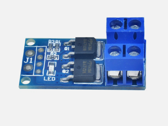
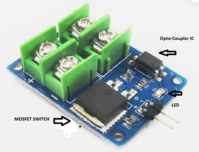
The dual MOSFET ignition output drivers, for powering COPs & external coil ignitors, (model TC-4424), are mounted on the Speeduino PCB. I therefore cannot use these for triggering the 4 off COPs, so the Speeduino PCB, remains "unmolested". The outputs of the four (4) off 4075 ICs, on my switching module, are highly unlikely to have enough current capacity, to trigger the COPs. I therefore used external MOSFET opto isolated modules, to switch the four (4) off COPs. I've hooked up the outputs of my Sequential to Wasted spark switching module, to four (4) off these small MOSFET modules. That's the MOSFET on the LHS, & the little IC on the RHS; is the opto coupler. These are available on ebay, & are very economical. I paid $ 1.62 each, off memory. You can even purchase a dual version of these, with two (2) MOSFETs mounted on the one PCB. For about $ 8.00, You can have four (4) MOSFETs, to switch your four (4) COPs, or ignitors. However, the dual ones, don't appear to have opto-couplers, for the input signal. I might just add four (4) opto-couplers to my switch module output, so that it doesn't matter if the MOSFET module used; does not have an opto-coupler built-in. The Opto-Coupler I generally use, is the MOC5007. This Opto has "hysteresis" built in, which makes the system, I've created; very "noise tolerant". The beauty of the both MOSFET modules, I depicted above; that they both have a little LED on the board; so You can see that a signal is being received from Sequential to Waste Spark switching module. I've only been able to find one aftermarket ECU that incorporates Waste Spark functioning, during cranking. That's the high end MaxxECU race ECU. Apparently, LINK ECU mentioned way back in 2021, that they were considering including it; in a future upgraded specs; but I don't believe that has been implemented as yet. Cheers Banjo