

Banjo
-
Posts
2028 -
Joined
-
Last visited
-
Days Won
98
Content Type
Profiles
Forums
Events
Gallery
Blogs
Everything posted by Banjo
-
Glad You are into it ! Hope is addictive, & not too despressing. I'd really be concentrating on the structural bits first, as they are the most important, after all. Shame to do all the surface & visual pieces, & then find later on, that there is a structural section, beyond repair, & that all the visual; non structural clean up, was in vain. A simple rotisserie would be good, so it is easy on your back. No fun working upside down, when You get to the underfloor area. Metal Rotisserie Wooden Rotisserie Cheers Banjo
-
Hi Tony, My guess is; that now You will want to calculate the new "compression ratio", of your 60 thou bored engine. This is a little more complicated, depending on whether you have flat top pistons; or pistons with domed or concave top faces. This calculation, should also take into account the thickness of the head gasket, once torqued down, to be truly accurate. Here is a variety of sites tackling this question, if Your interest requires this information. How to Calculate the Compression Ratio Obviously, if you bore the engine, & leave the combustion area in the head untouched; the compression ratio, will increase. Question is; by how much ? This link here on Rollaclub, from over a decade ago, might help ? https://www.rollaclub.com/board/topic/69246-4k-engines/ Cheers Banjo
-
The volume of a single cylinder is Pi x r squared x the stroke. 22/7 x bore/2 x bore/2 x stroke. For a standard 4K engine, the bore is 75mm & the stroke is 73mm Substituting these into the above equation give (22/7) x (75/2) x (75/2) x 73 = 3.1429 x 37.5 x 37.5 x 73 = 322638.33 cu mm Divide that by 1000 to obtain cubic centimeters & you obtain 322.64 cu cm. That is for one cylinder. To calculate that for 4 cylinders, simple multiple by four. 322.64 x 4 = 1290.56 cc, which is what the good book says the capacity is for a standard 4K engine. Now simply add 1.524mm (60 thou) to the bore dimension, & recalculate. 3.1429 x (75.00+ 1.524)/2 x (75 +1.524)/2 x 73 = 3.1429 x 38.26 x 38.26 x 73 = 335.85 cu cm Multiple that by 4 & you get a new volume of 1343.4 cc. Subtract the original standard volume = 1343.40 - 1290.56 = 52.84 cc. or an extra 13.21 cc to each cylinder's swept bore capacity. Yep, basically, the same as Simons calc. Cheers Banjo
-

ELECTRIC FUEL PUMP WITH SAFETY PRESSURE SWITCH
Banjo replied to knibusu's topic in KE70 Technical Questions
I'm intrigued now; as to why all three (3) brand new mechanical fuel pumps, mechanically failed; all with damaged diaphrams, in a short period of time; when You had utilised the spacer block to mount them off the engine block mounting point ? The only thing I could suggest; was that the curved arm on the aftermarket ones, was a different shape or profile, to the Toyota original supplied & fitted pump ? My KE30 with a 4K-U engine has been running a mechanical pump for 20 years, I've owned it, without issues. They are not real good at drawing/sucking, without priming; but once that line has got fuel in it, they never stop or fail; from my experience. Got me beat ! However, I applaud your determination to fit a good electric fuel pump, in the boot area, close to petrol tank. It is the way to go. P.S. In a petrol / carby engine, the fuel pump is one item, you can actually drive, without using one at all. Many years ago, in an olde English car, the S.U. fuel pump failed, in the middle of no where. A small plastic jerry can, was roped to the roof rack, & a plastic tube run from said plastic jerry can, to the carby fuel inlet. A quick suck on the tube to get the fuel running down the plastic hose, & we drove all the way from Brisbane to Sydney, without so much as a hiccup ! I think it is referred to, as "gravity feed". True story. Cheers Banjo -
ELECTRIC FUEL PUMP WITH SAFETY PRESSURE SWITCH
Banjo replied to knibusu's topic in KE70 Technical Questions
No, No, No ! New mechanical fuel pumps do not fail like that, or so quickly. I think I know what is your problem ? Not supplied with any of the new mechanical fuel pumps You have purchased in the past, is a fibre spacer, about 12mm think, that fits between the fuel pump flange, & the side of the engine block, where the pump fits. If you omit this spacer, the fuel pump arm is "too close" to the offset lobe on the camshaft, that operates the mechanical fuel pump. This means the diaphram in the pump travels too far up, & either tears the diaphram, or breaks the pump. Put the spacer back in, & your mechanical fuel pump issues will disappear, immediately. Some lots of replacement K Series replacement pumps are sold with two (2) off gaskets. They are not being generous. The two gaskets are for fitting to both sides of the spacer block. I've even seen one pump advertised, which includes the spacer block. Guaranteed to solve your problem ! Cheers Banjo

-
ELECTRIC FUEL PUMP WITH SAFETY PRESSURE SWITCH
Banjo replied to knibusu's topic in KE70 Technical Questions
Don't forget, that our friend here (Knibusu), does not have fuel injection. His car has a simple carby. These type of 12V fuel pumps only typically produce 4-6 PSI. They are however, much better at "pushing fuel" than sucking/drawing it; which is a good reason to locate the pump, in the boot area, close to the fuel tank. However, this "Facet" brand pump, is not a cheap pump; & is quite sophistcated. Apparently, as soon as there is sufficient back pressure it turns itself off, or reduces it's output, according to this discussion I found on the web, at the link below. I know even the early SU fuel pumps used to basically turn off, or reduce the flow, as my Dad had an early Morris straight 6 (like the Worsley 6/80), & the SU fuel pump was on the passengers side on the rear of the engine bay, & you could hear it ticking away, & changing it's beat. The SUs were not very good at sucking either. I think on the very first Minis, the SU was up front; but later Minis, had the SU, right at the rear, near the tank. https://www.4x4community.co.za/forum/showthread.php/19591-Facet-electric-pumps-Fuel-return Cheers Banjo -
ELECTRIC FUEL PUMP WITH SAFETY PRESSURE SWITCH
Banjo replied to knibusu's topic in KE70 Technical Questions
The more I think about this technique, the more questions it raises, in my mind. The motor racing industry, may well require such a device, but for a normal road car, the implications of low or lack of oil pressure, whilst driving, & the engine just shutting itself off, outside of your control; could be extremely dangerous. The oil safety light on the dash of most cars is really all that You require. Have a read of the comments at this link. https://classicbroncos.com/forums/threads/wiring-electic-fuel-pump.43215/ When you first turn the ignition key "On"; before trying to start the car, the dash oil pressure warning light comes on, which tells you, "that the oil press sensor is working". When you start the engine & the oil pressure is generated, the warning light goes out; & You definitely know that the oil pressure is present & working OK. I suggest, that if You are concerned, or interested about oil pressure, in your engine; that You fit an oil pressure guage, to your dash area. You will learn more about oil pressure watching that over time. I simply think, that providing your car & engine, the ability to shut down the engine, whilst You are driving; "outside your control", could be downright dangerous. eg: You are highway driving, at say 100 klm/hr. Your oil level in the engine, is a bit on the low side. You approach a big curve in the road, & the sideward force moves the oil in the sump, sideways; & the intake pickup for the oil pump, grabs some air, as it is now not totally covered with oil. An instantaneous switching of your oil pressure safety switch, turns the engine off. You are on a curve, at elevated speed. The possible ramifications could well prove fatal, if You lose control. I could not imagine a rally drivers, ever considering fitting such a protection device to their engine. That engine gives one cough, whilst drifting sideways with opposite lock, on a dirt road, among the trees, is a complete "no no" to my mind. I'm open to others point of view, but personally, I do not think, it is a useful addition, to your road car. P.S. When assembling a fully reconditioned engine, all the bearing areas, are "assembled wet", with oil. The engine may also be turned over by the starter motor, without spark plugs or ignition connected, so all oilways in the block & head are filled. The only other situation, I can imagine, which might require such an action; is if an engine has been sitting for years, & is being started for the first time. Remove the plugs & turn the engine over, on the starter motor, is a common precaution. On top of that the Facet electric fuel pump, is a fairly expensive & highly sophisticated fuel pump, which is self adjusting, & provides a constant pressure, according to the maufacturers description. Would like to hear others thoughts on this matter. P.S. As a matter of interest; where did you mount the Facet Electronic fuel pump ? Is it in the boot area, adjacent to the fuel tank, or up in the engine bay somewhere, close to the engine proper ? P.S.S. Is this a transducer for an oil pressure guage ? Cheers Banjo
-
ELECTRIC FUEL PUMP WITH SAFETY PRESSURE SWITCH
Banjo replied to knibusu's topic in KE70 Technical Questions
I really think there is something wrong with the circuit above, or the logic of operation. Did You obtain this circuit from this website link below ? https://www.jalopyjournal.com/forum/threads/oil-pressure-safety-switch-wiring-help.1112142/ Further down the page a relay is incorporated. I'll have a think about this. Is your purpose for fitting it, to not allow the engine to fire up, until the oil pressure during cranking, is enough to prevent a "dry cranking" situation. The needle valve in any carburetor usually stops any fuel from entering the carby, once the fuel bowl is full. The needle valve simply opens & lets more fuel in, once the fuel level in the carby bowel lowers slightly. This action keeps the fuel bowl constantly full, & to a certain level. Most engine regimes don't turn an electric fuel pump off. Are you trying to "stop the engine from starting", until the starter motor cranking, has built up some oil pressure ? As stated earlier, if You want to set this up as an accident scenario, where the fuel pump stops, on impact; then You need a G force sensor on impact switch, to turn the fuel pump off. I'll come back to You tomorrow, after I have a think about the logic behind this. I can see some need for an arrangement like this, in maybe a racing car; but not a road car. Cheers Banjo
-
ELECTRIC FUEL PUMP WITH SAFETY PRESSURE SWITCH
Banjo replied to knibusu's topic in KE70 Technical Questions
Nice diagrams ! I'm assuming that this engine has a carby, & is not fuel injected, which use much higher pressure fuel pumps. There are two types of electric low pressure fuel pumps for carby fuelled engines. There is the electric rotary motor type, which just runs all the time, & there is the diaphram type (like the old British SU fuel pumps), which only power up & pump, when the pressure on the outlet drops. The most common form of "emergency cut out" switch for electric fuel pumps is an impact type switch. These are usually rated at around 10G force activation, in case of an accident, or collision. Just because a car is in an accident; does not mean that the engine will stop turning. I've seen a crash, where the engine just sat there & screamed; & the only way was to remove a lead from the battery. The last thing You want in an accident, is to have a fuel pump, continuing to pump fuel onto a hot engine, & creating/causing a fire. I'd check the transport website in your area, as to what they stipulate. Cheers Banjo -
Not real sure what You are trying to advise ? When You turn the ignition key, to the start position, & the starter motor turns over; but when You release the key, the starter motor continues to turn ? I'd think it would more likely to be the starter motor itself. It might be that the throw-out solenoid, or something mechanical is worn, or at fault. Could also be an ignition switch mechanism gone ? First & easy test, as You think it might be electrical, is to remove the wire from the starter motor solenoid, & connect it to a 12V automotive bulb or test lamp to ground/earth/chassis. Test that it only lights, when the ignition switch is held against the return spring, in the "start" position. Not sure what You mean by, "I recently removed this wiring and I am not sure if it correctly done." The starter motor is permantenly connected to the +ve & -ve terminals of the battery. The starter solenoid, (within the starter motor) switches the +12V at the starter motor to the windings, inside the starter motor itself. Cheers Banjo
-
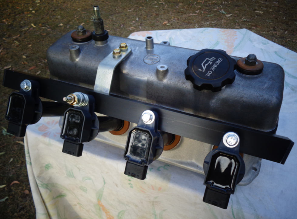
Should have the incremental rotary encoder arrive here this week, with a single "Z" pulse output, I can hopefully use as a CAS signal. I've decided to fit this dissy to my 4K-U engine in my KE-30, so I can do some real road testing on it, instead of on the 5K stationary test bed engine, in my workshop. I will need to change my single ignition coil over to COPs. I built a COP frame for the Denso COPs, a couple of years ago. It was a quick build in a couple of hours on a Sunday afternoon. That one is still in use on the Test Bed 5K engine stand. However, fitted to a road car, would require something a bit more rigid & strong, so I built one over the weekend, out of stock aluminium & few rivets & 6mm Riv-Nuts from Bunnings. It is quite rigid; as I pick up the whole head's weight, holding onto the aluminium bracket. Those two flat bar angled brackets from the rocker cove, are actuallt stainless steel. Just awaiting some DENSO 4 wire plugs for the COPs, so I can wire them all up. I hope to be able to feed the 3 wires to each COP, through the aluminiun channel, to keep it neat & out of sight. I've purposely made the COP mounting frame a little longer at each end, on purpose. It maybe; that on the engine, the frame vibrates a bit at a particular RPM, that might coincide with a resonant frequency of the frame & it's mounting brackets. If that eventuates, I can always run a couple of support bars down from the ends of the COP bracket, to the engine block below. Cheers Banjo


-
Hi All, I'm not into AI as yet, as I have enough on my plate each day, to keep me very busy. MicroSoft has added AI to a number of their products. I use MicroSoft WORD every day, in my business. The latest update of Word, includes an AI function called "Co-Pilot". Basically, You ask it to produce/write something about a particular subject, & it goes away, & in a very short time, will come back, with something it has created, based on it's scouring the web, & other resources at it's disposal, where it can "learn" about what You have asked it to do. So, I'm interested in upgrading older engines, with modern day ECUs, & precision control. Of late, I've been really investigating crank & camshaft triggering systems, & currently experimenting with using a incremental rotary encoder, installed inside a gutted dissy, (thanks Taz-Rx), to produce equivalent crank & CAS pulse for a Speeduino ECU. So in Microsoft Word I simply gave Co-Pilot this task . . . . . "Write an article on using an incremental rotary encoder as a triggering system for an automotive engine" Within about 5-10 seconds, Co-Pilot produced the following short discussion, about this subject (see below) _________________________________________________________________________________________________________________________________________________________________________ Incremental Rotary Encoder as a Triggering System for Automotive Engines Innovative Solutions for Precision and Efficiency Introduction The automotive industry has seen exponential growth and technological advancements over the years. One such innovation is the use of incremental rotary encoders in engine systems to enhance performance, precision, and efficiency. This article explores the application of incremental rotary encoders as a triggering system for automotive engines, highlighting the benefits, functionalities, and implementation methods. Understanding Incremental Rotary Encoders Incremental rotary encoders are electromechanical devices that convert rotational motion into digital signals. These encoders operate by generating pulses in response to movement, which can be used to determine the position, speed, and direction of a rotating shaft. The working principle involves a disk with evenly spaced markings and a light source paired with a photodetector. As the disk rotates, the photodetector reads the markings and converts the interruptions into electrical pulses. Types of Incremental Rotary Encoders There are several types of incremental rotary encoders, each suited for specific applications: · Optical Encoders: Utilize light sources and photodetectors. Known for high precision and resolution. · Magnetic Encoders: Employ magnetic fields and Hall-effect sensors. Suitable for harsh environments due to their robustness. · Capacitive Encoders: Use capacitive sensing technology. Offer good performance with low power consumption. Application in Automotive Engines Incremental rotary encoders can play a pivotal role in enhancing automotive engine performance by providing accurate and real-time data on engine components' positions and speeds. Here’s how they can be effectively utilized: Triggering System for Engine Timing Engine timing is crucial for optimal performance, fuel efficiency, and emission control. Incremental rotary encoders can serve as excellent triggering systems for engine timing by: · Crankshaft Position Sensing: By measuring the crankshaft's position, encoders can ensure precise ignition timing and fuel injection. · Camshaft Position Sensing: Encoders can monitor the camshaft's position to synchronize valve operation with piston movement. Speed and Direction Monitoring Incremental rotary encoders can provide real-time data on the rotational speed and direction of various engine components. This information is vital for: · Engine Control Units (ECUs): ECUs can adjust engine parameters based on the data received from encoders, optimizing performance. · Diagnostics: Encoders aid in diagnosing issues related to engine speed and direction, facilitating timely maintenance interventions. Implementation in Automotive Systems Implementing incremental rotary encoders in automotive engines involves several considerations to ensure seamless integration and optimal functionality. Selection Criteria Choosing the right encoder depends on various factors: · Environmental Conditions: Opt for magnetic encoders in harsh environments due to their durability. · Resolution Requirements: Optical encoders offer high resolution, making them ideal for applications requiring precision. · Power Consumption: Capacitive encoders are recommended for systems where low power consumption is crucial. Installation and Calibration Proper installation and calibration are essential for the accurate functioning of encoders: · Mounting: Encoders should be mounted securely to prevent vibrations that could affect signal accuracy. · Alignment: Ensure that the encoder's disk is aligned correctly with the light source or magnetic sensor. · Calibration: Regular calibration checks are necessary to maintain optimal performance and accuracy. Benefits of Using Incremental Rotary Encoders The adoption of incremental rotary encoders in automotive engines offers several advantages: · Enhanced Precision: Accurate measurements of position and speed lead to improved engine timing and performance. · Real-time Data: Immediate feedback allows for timely adjustments and diagnostics. · Reduced Emissions: Optimized engine operation can contribute to lower emissions and better fuel efficiency. · Cost-effectiveness: Improved diagnostics and maintenance reduce long-term operational costs. Challenges and Solutions Despite the benefits, there are challenges associated with integrating incremental rotary encoders in automotive engines. These include: · Signal Interference: Electrical noise can interfere with the signal. Shielded cables and proper grounding can mitigate this issue. · Mechanical Wear: Continuous rotation can lead to wear and tear. Regular maintenance and high-quality materials can reduce this risk. · Temperature Variations: Extreme temperatures can affect encoder performance. Choosing encoders with suitable temperature ratings can help. Conclusion Incremental rotary encoders are revolutionizing the way automotive engines are monitored and controlled. Their ability to provide precise and real-time data on the position, speed, and direction of engine components makes them invaluable for optimizing engine performance, enhancing fuel efficiency, and reducing emissions. By understanding the types, applications, and implementation methods, automotive engineers can harness the full potential of incremental rotary encoders to drive innovation and efficiency in the automotive industry. _______________________________________________________________________________________________________________________________________________________________________ Next time I might ask it a question a little bit harder . . . . . like "How do You remove the camshaft sprocket cover, on a Toyota K Series engine, without removing the sump ?" Cheers Banjo
-
Hi John, Things are looking up, & possibilities with the guard & bonnet. To make You keep feeling good about your project, I suggest You have a look at this Corolla waggon, still in daily use in South America. It's a tradies daily drive ! https://www.curbsideclassic.com/blog/cc-capsule/cc-outtake-1977-toyota-corolla-wagon-one-hard-working-corolla/ Enjoy ! Cheers Banjo

-
Hi John, Just to inspire You, here a couple of pics of a couple of restored E10 Corolla 2 door waggons I found on the net. Enjoy ! Cheers Banjo


-
I went out in the shed tonite, & found a 3K early dissy, which had the narrow, yet deep main body. This dissy was in very good condition, but I gutted it completely, so I could determine, if the incremental rotary encoder, would sit neatly inside. Ah Yes ! I even found a jam jar lid, in my wife's kitchen cupboard, (She is out tonite) that fits perfectly, like it was made for it. I would have liked a dissy body, with a replaceable ball race bearing at the base; like the one in the 4AGE distributors, instead of the phosphor bronze ones fitted to all K series engines, I believe. However, this dissy shaft & sleeve bearing are in remarkable condition, so very happy with the fact, that the two parts, manufactured, many decades apart, are so complementary. Just have to be patient now, until the Omron incremental rotary encoder, with a single "Z" pulse per revolution arrives here, & I can take it to the next stage. Cheers Banjo


-
4K-C engine stalling while down shifting, need help!
Banjo replied to Silent Icecream's topic in KExx Corolla Discussion
That's a very; very good sign, it is the clutch. You'll know instantly, once you get the full cable assembly out, & try to move the inner cable back & forth, whilst holding the outer sheath, in the other hand. I've seen them so tight, that you had to squirt WD40 down them, & wriggle the inner back & forth, before it would free up. Trick is, once You get it free up; to add copious amounts of light oil down inside the sheath, until it is free & offers no resistance. Cheers Banjo -
It occurred to me, that there has to be someone out there in the big wide world, who has also seen the potential, of using an incremental rotary encoder, to basically be, an automotive "trigger wheel", & CAS signals, for an ECU's inputs. I scanned the internet, & only found one . . . https://forums.ni.com/t5/LabVIEW/Using-rotary-encoder-position-to-trigger-an-analog-pulse/td-p/2017540 If anyone reading this has come across any other similar efforts "on the web"; I'd me most grateful, if You could put a "link" in this discussion. Cheers Banjo
-
Welcome Aboard ! If You want a new Carby at a cheaper price; then ebay is your friend there. They seem to all be around the $ 180 - $ 220 Here in Australia. Ebay 4AFC Carbies I'm assuming Your Rolla has a 1.6 litre engine, in it ? Cheers Banjo
-
4K-C engine stalling while down shifting, need help!
Banjo replied to Silent Icecream's topic in KExx Corolla Discussion
Did this start to happen, all of a sudden; where before it was working perfectly ? Or is it something, that has been getting gradually worst over time ? Altezzaclub's suggestion is the most likely; caused by the clutch cable inside the outer sheath, needing a good clean. Take the clutch cable out completely, & hang it up in a vice, by the outer sheath, at one end. Add light oil down the cable whilst moving it up & down, by hand. Put as much oil in as you can; & leave it hang overnight. Once it is free, oil it generously, & reinstall. Even if it doesn't fix your problem, it a good thing to do to your Rolla, every couple of years. There is a couple of guys on this forum, over the years, who have put in hydraulically actived clutch operation, but it involves a lot of mods. Cheers Banjo -
MkII dissy, with a "incremental" encoder, is now underway. Research yesterday, indicated two "road-blocks"; with the concept of using an "absolute", rotary encoder. 1. One was the cost. The "absolute", type of rotary encoder are far more complicated; "internally", & more difficult to manufacture; hence the increase in cost. 2. Second, was the need for a lot more electronics; & possibly a small micro processor & coding, to indentify & grab that one pulse, to utilise, as a CAS signal to the ECU. Bear in mind, that I haven't considered using this dissy in a "wasted spark" system. I have tackled the sequential control of injection & ignition initially. You can easily make a "sequential" system, operate in 'wasted spark"; but not necessarily; the other way around. Altezzaclub & I had discussed this previously; & He suggested that as the second output of the "incremental" rotary encoder was not utilised; that maybe, we could "block out, 359, of the 360 windows for the optical encoder, & just use the remaining one, & it optical sensor, as the CAS signal. I resisted this suggestion; knowing how relatively tiny the 360 "windows" will be; within a disk or ribon, fitted inside a circular structure, that is just 35mm in outside diameter. However, I've decided to take the step, & dissemble the existing incremental encoder, & take a look, & see if this is a possible alternative. I bit of reading, on the net, revealed that some incremental rotary encoders, have a single "Z" output, for internal use, to zero the processing, once per revolution. (Not the one I purchased) If that output, is accessible, & brought out, it may in fact, be utilised as a CAS signal. Fingers crossed. ! - - - - - - - - - - - - - - - - - - - - - - - - - - - - - - - - - - - - - - - - - - - - - - - - - -- - - -- - - - - - - - - - - - - - - - - - - - - - A few hours later - - - - - - - - - - - - - - - - - - - - - - - - - - - - - - - - I dissembled my incremental rotary encoder, & my suspicions were immediately realised. The disk was so small; the slots were so tiny; & there was not a single slot in sight with a light sensor, that could create a single pulse pulse per revolution. I carefully put it back together. This encoder I had ordered had 360 slots in a circle. However, you could order them, with 1000 slots; so I just cannot imagine, how narrow they must be. I was however, bolstered by the fact, that the bearing in the incremmental encoder, I've be using, was very substanial, & could work reliably in a distributor on an engine, with lots of vibrations. After a cup of coffee, I decided to see if any manufacturers, produced a incremmental rotary encoder, with a Z single pulse. There were quite a few, but they were all hundreds of dollars each. I then thought, there has got to be someone in China, making these incemental rotary encoders, with 360 pulses per revolution, & a "Z" pulse. So off to ebay, & there they were; in a variety of different pulses per revolution, but with a Z pulse once per revolution, which came out in the wiring harness/lead. Things were looking up, so I read as much as I could, about this particular brand series. They were dearer than the one I had, but I did manage, to find one, with the exact specs I wanted, in China, with Speedpak delivery, for about $ 45.00. So it's ordered, & should be here in 1-2 weeks time. When I looked up this rotary encoders outside dimensions, it is almost the same size as the current one I'm using. As I had the one here; now out of the distributor, I took it over to the shed, & found a gutted K series dissy case, which we refer to as the "narrow" one. It fitted inside, with room to spare. So don't throw out any olde K Series dissies, You might have. They may yet live; to find a new purpose in life. Cheers Banjo


-
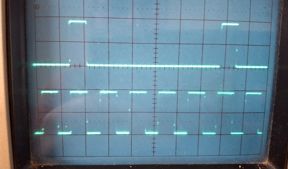
I've had some success, in the next stage of the development of a Trigger Wheel, & CAS signal, from within a K Series dissy. The Bosch K Series dissy was used, because they are physically larger in diameter, than the more common K series dissy body. The rings of rare earth magnets worked, but did present some issues. There are a couple of incremental rotary encoders used in industry; & the education industry, that provide an identical output to the rare earth magnets & Hall Sensors, but are a "drop in" item. Rotary encoders, can provide outputs, that can be used to indicate the rotational speed of the encoder; the direction of travel of the encoder; & the actual angular position, at any time. An industrial grade absolute encoder, can be quite expensived, but the small "educational" incremental ones, for teaching concepts; are less than $ 30.00 ea. As can be seen in the three pics below; they are relatively easy to mount, in the dissy. If You want to read more about encoders, in general, then head across to this link. https://en.wikipedia.org/wiki/Rotary_encoder These encoders come in a variety of models, with different numbers of pulses per single rotation. Because we are interested in angular movement of the distributor, & everything ECU wise is related to degrees BTDC etc.; I chose, & ordered; an encoder that provided 360 pulses per rotation. The encoder has two of these outputs, slightly off-set angularly, so that it is possible to work out which direction, the encoder is rotating in; although that is of no interest to us, in this dissy application, as the dissy only rotates in a clockwise direction. (more on that second output later) However, most ECUs accept pulse trains from trigger wheels, that produce pulses of 24/36/60/72 pulses per single rotation, of the crankshaft. As the dissy only rotates once per two (2) revolutions of the crankshaft, then we are only interested using 180 of those dissy encoder pulses, & we set the ECU up, as if these pulses are being derived, from the crankshaft. I then decided to see if I could divide the 180 pulses per "effective crankshaft revolution", down to one of these above common ECU trigger wheel numbers, for a crank shaft rotation. Pulse chains in electronics, can only be easily divided by whole numbers. 180 divided by those trigger wheel numbers are (180/24 = 7.5; 180/36 = 5; 180/60 = 3; & 180/72 = 2.5; 180/4 = 45. We can only easily divide by whole numbers in electrionics, so dividing the pulse train by 3 or 5 produced the equivalent of a 60 or 36 tooth crank trigger wheel. Most ECU manufacturers, advise that crankshaft trigger wheels between 24 to 60 teeth, provide best resolution. So it didn't take long to then produce these switchable trigger outputs, to an ECU. Oscilloscope grabs of the primary (360) & divided by 3 & 5 pulses, are below. I had left my single CAS magnet & Hall Effect sensor in the base of the dissy body, so do have a working system. However, the rotational encoder sits up pretty high, so I cannot create my low profile dissy, with my "jam jar" lid. Could I possibly, use that second pulse chain of the encoder, to produce a single CAS signal ? Unfortunately; not with this particular encoder, but could be possible with a absolute positional encoder, where each of the 360 pulses per rotation, creates a unique number. We could only look for just one number, & use that pulse as the CAS pulse. However, it may be simpler than that, as an absolute rotary encoder has a single pulse per revolution, that resets the counters. That may make a perfect CAS signal, if brought to the outside of the encoder. All I've got to do, is find an "absolute" rotary encoder, in a small footprint, at a reasonable price. Simon down in Tassie, is sending me up a K Series Bosch dissy, so I can then try this theory out, in practice. It may be; that ultimately, we may be able to even accomodate this angular encoder, into one of the "narrower", olde K Series dissies. All good fun ! Cheers Banjo


-
Hi John, Just looking at those marvellous photos again, I think I spotted a silver "Shilling", sticking out from underneath the drivers seat, that may defray the resto costs a little. Then, again I might be wrong. . . . . . . . . It may well turn out to be a "sixpence piece"; . . . . . . . or; just a washer ! Cheers Banjo
-
Hi John, Welcome aboard ! Thanks so much for this post, & all the pictures. Excellent story. Truly amazing ! So whereabouts is this relic from the "Toyota past" residing ? I see it is RH drive, so my guess is in rural Australia, or New Zealand. I note it has a push button radio. Wouldn't it be great if it still worked ? It's a great shame, the meeting of "Mazda & Toyota" on the passenger side front area. Because they are so simple, it won't be that hard to get it going again. The big question, will be how many $$$$$$ are needed to get that body rigid again. It's the inside bits in channels etc, where You can't see; that will be the real places, which will be crucial whether it can be restored. I'd be placing it on a concrete garage floor, & removing the wheels, one at a time; & jacking up that corner with a jack, & see what the body's creaks & groans tell you. Nothing is really not doable; but at what cost ? You are lucky though; that all the glass is there. Even your sister's attack on the front guard, could probably be returned with a good metal worker. Would love to hear what the next chapter will be for your "family treasure" ? Cheers Banjo
-
The Cherry ZF sensor You have purchased, is one of the best available, & usually very expensive here in Australia. It does not however, come with a built-in LED to indicate it is working & producing an output, when You place the sensing face close to a ferrous metal object like your vertical pin. They are generally utilised to sense ferrous teeth on a trigger disk, as depicted on the spec sheet. As your ferrous pin, has a curved surface facing the sensing surface of the Hall Sensor, it may well need to be a bit closer to the pin, than the 1.5mm, the spec sheet indicates for the gap. The only way, is to test it. As the Cherry unit does not have a built-in LED, You are going to have to hook up an external one, across the output of the Cheery Hall Sensor, as per my sketch below. You will need a small 6 or 12 volt battery to power it. The frequecy response of the Cherry Hall Sensor of 15kHz, makes it idea for this application. Most commonly, these sensors are used to pick up ferrous 30-60 teeth on a trigger wheel, attached to the crankshaft pulley. However, in an application like distributor body, where the distributor rotates at half the speed of the crank; & only has one tooth per rotation to sense, it is more than suitable for your application. So get yourself an automotive LED bezel lamp, suitable for 12 volts, at an auto store. These will already have a resistor, inside the lamp, in series with the LED, as the LED only needs 2-3 volts across it; (depending what colour they are), to light up. Detach the Hall Sensor from the dissy body, & then place various sized bolt heads, washers etc., close to the sensing face, & get a feel for how close it has to be, before the lamp is turned on fully. Then put it back into the dissy, & move it as close as necessary, to get the LED light to come on reliably & consistently. Let us know how You go. Cheers Banjo


-
Couple of questions ! What is the model number of the Hall Sensor You are using ? Is it a model that detects north or south poles of magnets; or is it one that detects ferrous metal targets ? Does the Hall Effect sensor have an LED light, built into the rear, where the cable enters the Hall Sensor. The setup You have there, maybe permanently switched on, depending on how sensitive the Hall Sensor is, & whether the "steel base", from which the pin protrudes is too close to the sensor, whilst it rotates. Nomally, You connect the DC supply voltage across the two (2) wires, that supply the Hall Sensor, with a DC voltage between 5-12V DC. Then rotate the dissy, & see whether the LED turns on & off, when the vertical pin passes the sensing face of the Hall Sensor. If You have model number for the Hall sensor, then list it here, & I can look it up, & see what type it is. Be careful when connection it up; as some Hall Effect sensor colour codes are a bit unusual. I've got some here, where the "brown" wire is +12Vdc, "black", is the output wire; & blue is the -ve wire. Cheers Banjo


