

Banjo
-
Posts
2023 -
Joined
-
Last visited
-
Days Won
97
Content Type
Profiles
Forums
Events
Gallery
Blogs
Everything posted by Banjo
-
Hi Daniel, Welcome aboard ! The horn not working is a perennial problem, that most come across, at some time or other. I don't think that model had a horn relay. Does your Rolla have one or two horns ? Easy to test if the horns actually work or not, by running a wire from the battery to each horn's feed wire, & make sure that they actually work. In fact, it is a really good idea, to fit a horn relay, so the horn button wiper ring carbon contact, is only handling the relay current. The little carbon brush, wears down until, it's spring won't hold it against the ring. Short term, You might get it to work, by "stretching" the fine spring a little. You'll have to remove the steering wheel, to accomplish that. You'll need the wiring diagram, to work out which coloured wire is which, on the wiper motor on the engine fire wall. Again, You should be able to test the wiper motor, at the firewall, just in case it is the motor itself; & not the switch. The lever assembly do wear out, & I remember replacing mine years ago. Mine does not have an intermittent setting for the wipers. Here is a link, that may help You. https://www.rollaclub.com/board/topic/72751-ke55-wipers-not-working/#comments Cheers Banjo
-
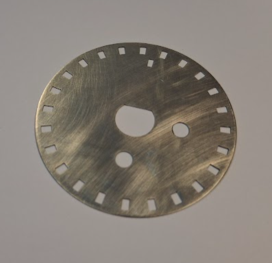
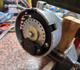
The incremental rotary encoders, I came across; with 360 pulses per revolution, seemed like a perfect way to produce a triggering system; physically small enough that it could fit inside an existing distributor body. This would mean that anyone that was handy; could "gut an olde dissy", & simply fit an encoder; & then replace the dissy on the K series engine. When I did my experiments on a 5K engine, with various aluminium disks & magnets, with Hall effect sensors; I had an engine on a test stand in my garage; & access, was very easy. Doing the same thing, with the engine in the car, could be very difficult; as every time You needed to run it, you'd have the replace the radiator, & maybe the grill. Simply removing the olde dissy, & replacing with another, is a relatively easy undertaking. However, my tests with the rotary encoders, had some side effects, resulting in pulses produced that "wavered around", on their leading & trailing edges. Most ECUs, trigger off a leading edge of a pulse, not the height or width of the pulse. After all; the ECU is only interested in the frequency, or time difference between pulses, to calculate accurately; the RPM of the engine. The incremental encoders I was using had 360 pulses per revolution, which being driven, by the camshaft, resulted in a resolution of one pulse per every 2 degrees of crankshaft revolution (which is extremely good). However, the leading edges of those pulses were not stable. This could well be the mechanics of how the pulse were developed inside the encoder; or the induced vibration; as the distributor enclosing the encoder, is firmly part of the engine block. Once I opened up an encoder, & witnessed how small the windows were in a tiny wheel, it all became very clear, to me, where the problem lay. Anyone, who has ever played with, or read about the issues with Nissan & Mitsubishi twin OHC motors; that used CAS's driven by a camshaft, will be aware of what they describe as "timing chatter". This was particularly observable; when the optical trigger S.S. disks in the CAS; had 360 little optical slots, around their outer edge. However, others on RollaClub, have fitted the "rotary optical encoder", from Nissan SR20 CAS units to the Bosch dissy, that Toyota used on some early K series engines. It was a little wider in diameter, than the more common Denso dissy body. The picture below, indicates, it fits, like it was made for this dissy. Brand new optical transducers, are commonly available, on ebay, Amazon, & AliExpress, & are relatively inxpensive. These however, do not come with the 50mm S.S. laser cut, or punched slotted disk. The most commonly available ones are a 24-1 & a 360-1. There are 36-1, & 60-1 models of these slotted disks, but they are very hard to find. I'm currently trying to find an overseas source. A 72-1 or even a 120-1, would be really nice, if I can get hold of one. 50mm dia. S.S. disk 24-1 Optical So as soon as my brand new optical sensor arrives in a week; I'll start some bench testing, with my oscilloscope, to see if the result; does not suffer the issues, I've had with the incremental rotary encoders. So while awaiting this SR20 optical encoder, I wondered if what I'm proposing; is the very best way of triggering an ECU. So I asked AI; & this is word for word; what it produced. ____________________________________________________________________________________ The Pinnacle of Triggering Systems for Aftermarket ECUs in Automotive Engines Precision, Speed, and Reliability in Modern Engine Management Introduction In the pursuit of automotive performance, reliability, and efficiency, the role of the engine management system stands paramount. At the heart of any sophisticated engine control unit (ECU), whether factory or aftermarket, lies the triggering or “engine position sensing” system. For tuners, racers, and engineers seeking the utmost in accuracy and speed, the selection of a triggering system is a foundational choice. This document explores the very best, most accurate, and highest-speed triggering systems available today for aftermarket ECUs, dissecting how they work, why they excel, and which applications benefit most from their precision. The Function and Importance of Triggering Systems Triggering systems in automotive engines provide real-time feedback on crankshaft and camshaft positions. This information allows the ECU to precisely control ignition timing, fuel injection, variable valve timing, and other functions critical to high-performance and emissions-compliant operation. Any inaccuracy or latency in the triggering signals can result in poor engine efficiency, reduced power output, or even engine damage in extreme conditions. Key Requirements of High-Quality Triggering · Accuracy: Ability to resolve crank and cam position with minimal error, down to fractions of a degree. · Speed: Fast response with minimal latency, especially important at high RPMs (upwards of 10,000-15,000 RPM in racing engines). · Noise Immunity: Reliable operation in the presence of EMI/RFI and electrical noise common in modified vehicles. · Compatibility: Ability to interface with a wide range of aftermarket ECUs. · Reliability: Robustness under temperature, vibration, and environmental stress. Overview of Common Triggering Technologies · Inductive (VR) Sensors (Variable Reluctance): Generate AC signals as a toothed wheel passes a magnetic pickup. Robust and simple, but resolution and accuracy can suffer at very low or very high RPM. · Hall-Effect Sensors: Output a digital square wave as a ferrous target passes the sensor. Highly accurate at all speeds, with clear on/off transitions that are easy for ECUs to interpret. · Optical Sensors: Utilize a slotted disk and an LED-photodiode pair. Offer high resolution but can suffer from contamination and are less common in modern automotive applications. While VR and Hall sensors are both widely used, the combination of a well-designed toothed wheel and a Hall sensor is often considered the gold standard for aftermarket high-performance ECUs. The Best: High-Resolution Multi-Tooth Reluctor Wheels with Hall-Effect Sensors The leading solution in the aftermarket today is a high-resolution multi-tooth crank trigger wheel (such as a 36-1, 60-2, or similar) coupled with a precision Hall-effect sensor. This setup is favored by top ECU manufacturers (Motec, Haltech, Link, Emtron, Syvecs, and others) for its blend of speed, accuracy, and robustness. How It Works A multi-tooth wheel (often mounted to the crankshaft) has a series of teeth (e.g., 36 or 60), with one or two teeth omitted (“missing teeth”). The Hall sensor reads the passing teeth, generating a digital signal that the ECU interprets. The missing teeth serve as a reference for the ECU, allowing it to determine absolute engine position each revolution. When paired with a camshaft position sensor (also Hall or VR), the ECU can establish engine phase, enabling full sequential injection and ignition control. Why This System Excels · Exceptional Resolution: With more teeth, the ECU can “see” the crankshaft in finer increments, allowing for precise timing adjustments—critical at high RPM. · High Speed: Digital Hall-effect sensors can process rapid tooth passages even at extreme engine speeds, supporting applications up to and beyond 20,000 RPM. · Clean Signal: Hall sensors are less susceptible to noise and are easier to wire and calibrate than inductive sensors. · Self-Calibrating and Adaptive: Modern ECUs automatically adapt to signal characteristics and compensate for minor variations in wheel manufacturing or installation. Common Trigger Patterns · 60-2: Sixty teeth on the crank, with two missing. Popular in BMW, Volkswagen, and modern performance engines. · 36-1: Thirty-six teeth, one missing. Common in Ford and many racing applications. · 24-1 or 24-2: Used in some Japanese performance engines. The more teeth, the higher the resolution, but also the greater the processing demand—modern ECUs easily keep up. Comparative Analysis: Why Not VR or Optical? While variable reluctor (VR) sensors are robust and cheap, their analog nature can result in signal degradation, particularly at very low or very high RPMs. This can cause starting issues or misfires at high engine speeds. Optical sensors, though precise, are vulnerable to contamination and less reliable in the harsh automotive environment. Hall-effect sensors with multi-tooth wheels strike the best balance—digital, precise, robust, and widely supported. Integration with Aftermarket ECUs Modern standalone ECUs such as Motec M1, Haltech Nexus, AEM Infinity, Link G4X, Syvecs S7, and Emtron KV utilize advanced digital filtering and adaptive algorithms to extract the most from high-resolution Hall-based trigger systems. They can instantly detect crank/cam direction, synchronize rapidly, and support variable valve timing and complex multi-stage ignition/injection. Features now often include: · Real-time diagnostics of trigger signal health · Automatic compensation for sensor drift or minor wheel imperfections · Support for multi-channel (dual cam, quad cam) setups · Advanced fail-safe and redundancy modes Emerging Technologies and Future Trends Advanced magneto-resistive (AMR) sensors and integrated digital encoders are being explored, offering even more granular resolution and self-diagnostics. Wireless trigger systems may appear in the future, but as of today, the Hall sensor plus multi-tooth wheel remains the industry’s fastest, most accurate, and most reliable choice. Installation and Best Practices To maximize the benefits of a high-speed, high-accuracy system: · Mount the trigger wheel as close to the crank centerline as possible to minimize runout. · Use shielded, twisted pair wiring for sensor signals to further reduce noise. · Always follow ECU manufacturer recommendations for sensor voltage (often 5V or 12V) and pull-up resistor values. · Test signal integrity across the full RPM range before tuning aggressively. Real-World Application Examples Motorsport – Formula One and Endurance Racing: Modern F1 engines use proprietary high-resolution digital encoders, but for high-end club and professional motorsport, the 60-2 Hall system is the de facto standard. Street and Track Tuners: Cars retrofitted with ECUs like the Haltech Elite or Motec M1 see massive improvements in driveability and maximum RPM when switching from OEM VR sensors to Hall/multi-tooth setups. Conclusion For those seeking the ultimate in engine control, the pairing of a high-resolution multi-tooth trigger wheel (such as 36-1 or 60-2) with a premium Hall-effect sensor delivers the very best in speed, accuracy, and reliability. This combination is supported by every leading aftermarket ECU, is robust to electrical and environmental noise, and provides the foundation for precision tuning and advanced features. While technology continues to evolve, this system remains the gold standard for modern performance and racing engines. ____________________________________________________________________________________ Cheers Banjo
-
I have a friend down in NSW, up Gosford way, who is in the final stages of finishing off an SR20 Nissan engine rebuild, with all the good stuff, as part of the engine makeover/upgrade. He wants to drop it into a Corolla KE70 body; but is having great difficulty, locating a reasonable KE70 body. He doesn't mind if it is just a shell, as long as it hasn't got extensive rust. Obviously, He won't be put off, if it doesn't have an engine in it, as He has His SR20, just about ready to drop in. Obviously, if it was in the Sydney greater area, that would be ideal; but is prepared to transport it from anywhere, within a days drive ! If You have seen a "reasonable one", at a wreckers somewhere; give me a yell, & I'll pass the info onto Him. Many Thanks ! Cheers Banjo
-
https://www.youtube.com/watch?v=CULI2VClEm8 Cheers Banjo
-
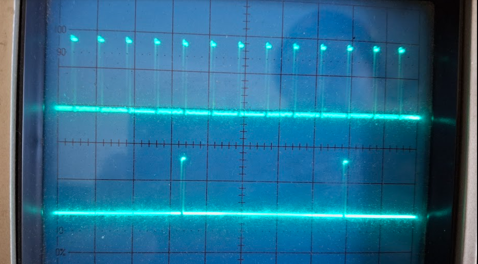
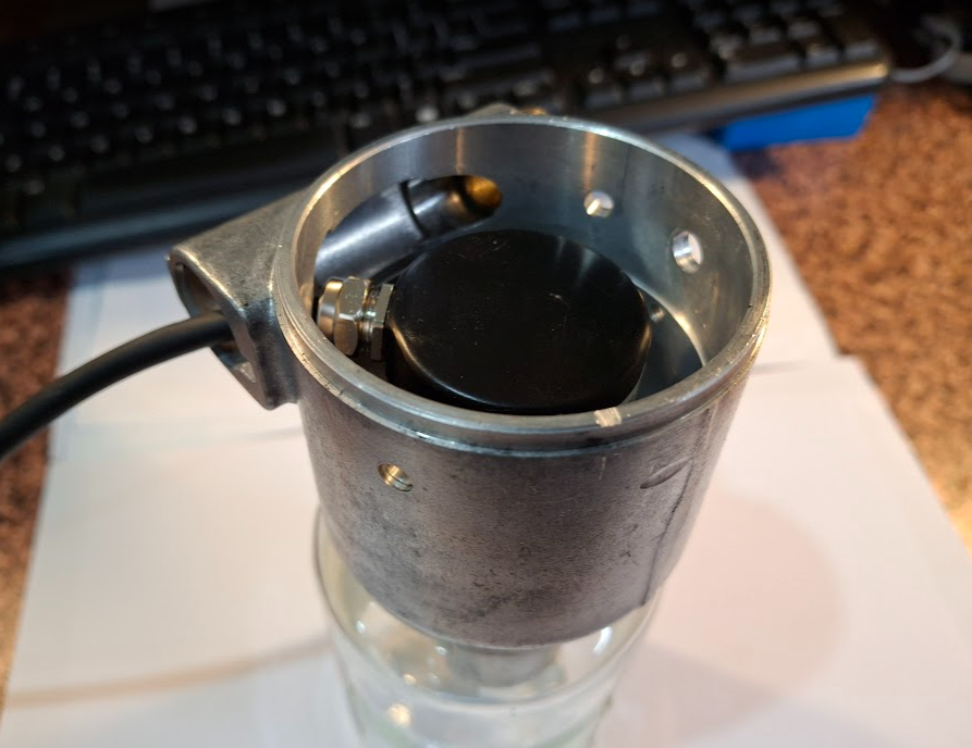
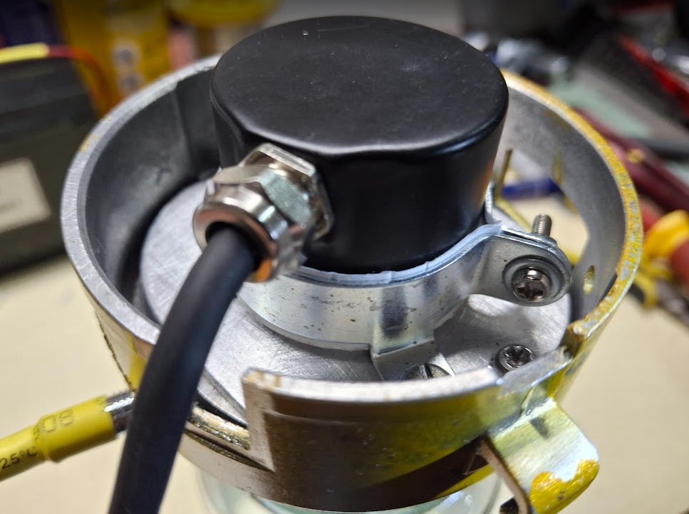
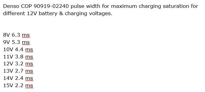
Haven't had a lot of time, to persue this project lately, & have run into a few issues with my Rotary Encoder with a Z Pulse. The first one, with a "Z" pulse output, that I purchased; I accidentally killed with an incorrect connection, whilst testing it. I had to await a second one to arrived, & that worked; but I could not get nice stable pulses from it. I tried all sorts of ways to stabilise it, but came to the conclusion; that the "timing jitter" & unsteadness, of the CRO traces, were in fact a result of the vibration, inside the rotary encoder itself. This encoder, was pimarily utilised, because I had discovered, they were available with an additional single "Z" pulse, per revolution. Maybe all rotary encoders are not all built equally. I did not remember, having this issue, with the very first rotary encoder I purchased; that did not have, the single "Z" pulse, per revolution. At the weekend I pulled out the original Bosch dissy I had fitted this encoder to, along with the single CAS pulse I had built in the base of the dissy. The whole aim of using an encoder, with a "Z" pulse; was to avoid having to create a CAS pulse, & to fit the rotary encoder, completely, deep inside a narrow Corolla dissy. As it turned out, the rotary encoder, still stuck out high a bit; as I I had to fit a tiny rotary flexible shaft joiner, between the rotary encoder & the dissy shaft, which had to be turned down a bit. Getting the two shafts, which are slightly different in diameter; to be completely concentric, needed patience. Got it all working well, & there is no jitter or instability from the 360/6 pulses per dissy revolution; which just goes to prove that all rotary encoders are not built the same. The CRO traces show a steady & reliable trace of pulses. The top trace is the output of the encoders 360 pulses per revolution. The bottom trace is after the a divider has reduced that number to 60 pulses per distributor revolution. As the distributor turns only once, for two rotations of the crankshaft, then 180 pulses divided by 6 = 30 trigger pulses for each revolution, of the crankshaft. If it works well, I will decrese the division of the 360 off pulses to 3, which will produces 120 pulses per dissy revolution, which will equate to a 60 tooth trigger wheel, fitted to the crankshaft. Most ECU setups, allow you to nominated whether the pulse train originates from the cam-shaft, or crankshaft. Just have to hook it up to the Speeduino & COPs, & setup the COPS charging rate times per system voltage table; in TunerStudio, so there is no chance of overheating the COPs. Cheers Banjo
-
There are others on Rollaclub, over the years, that have used the Wade 169 32/36 cam grind, who have advised they were good. Just search Wade cams on Rollaclub;, & You should be able to read others comments about the Wade cam you are using. Some of these posts go back over 15 years. The other question I didn't ask You, in my previous post; was whether your 5K engine has hydraulic lifers, or have been replaced with solid lifters. Cheers Banjo
-
Hi Oscar, Too much advance; can cause pinging, at that part of the rev range. A simple timing light, & a bit of "white out", on the crankshaft pulley, & timing mark; will tell you, if that's the issue. However, there are a few other things that can cause "pinging", & knocking at high revs; besides it being simply the result of too much advance. This is what the "internet library" (AI), has to say about it. Can Engine Knocking at High RPM Be Caused by Excessive Ignition Advance? Understanding the Link Between Ignition Timing and Engine Knock Engine knocking, also known as detonation or pinging, is a phenomenon where fuel combusts prematurely or unevenly within the combustion chamber of an internal combustion engine. This can lead to a characteristic metallic "knock" or "ping" noise, reduced efficiency, and, in severe cases, engine damage. Ignition Timing Explained Ignition timing refers to the point in the engine's cycle when the spark plug fires to ignite the air-fuel mixture. This is typically measured in degrees before top dead center (BTDC), indicating how far in advance of the piston reaching its uppermost position the spark is triggered. An optimal ignition advance ensures that the peak pressure generated by combustion occurs slightly after top dead center, maximizing power and efficiency. However, if the ignition is too far advanced, the peak pressure occurs too early, forcing the piston downward while it is still traveling upward, which can lead to abnormal combustion events. High RPM Operation and Knocking At higher revolutions per minute (RPM), the air-fuel mixture has less time to combust completely. Engines are typically designed to run more ignition advance as RPM increases to compensate for this reduced combustion time. However, there is a limit to how much advance can be safely used. If ignition timing is excessively advanced at high RPM: · The spark plug fires too early, increasing cylinder pressure and temperature before the piston reaches top dead center. · This can ignite the remaining mixture prematurely or cause multiple combustion fronts, which collide and result in knocking. · The tendency for knocking increases if the engine is under heavy load, running lean, or using low-octane fuel that is less resistant to pre-ignition. Symptoms and Consequences Knocking at high RPM caused by too much ignition advance can manifest as: · Distinct metallic pinging or knocking noises under acceleration or sustained high RPM operation · Loss of power and throttle response · Increased engine temperatures · Potential piston or valve damage if the condition persists Diagnosis and Correction If engine knocking is observed at high RPM, it is important to: · Check and, if necessary, retard ignition timing in the problematic rev range · Ensure the engine is running the correct fuel grade · Inspect for other causes such as excessive compression, carbon buildup, or overheating · Use a timing light or engine management system diagnostics to verify actual ignition timing under load Conclusion In summary, yes, knocking in an engine at high revolutions can result from too much ignition advance in that part of the rev range. Proper ignition timing is critical to preventing knock, maximizing performance, and protecting the engine from damage. If you suspect ignition timing is the cause of knocking, it is advisable to consult the vehicle's service manual or a qualified mechanic to adjust timing appropriately. ____________________________________________________________________________________________________________________________________________________________ I'd have to look up how agressive the timing is on a Wade 169 cam, as that will also effect the valve & the fuel entry to the combustion camber. There is also the possibility, that in the reassembly of the engine the valve timing is out a little by incorrect fitting of the timing chain, & it's markings on the camshaft sprocket at TDC. If You pull out all the spark plugs, & take the rocker cover off, you should be able to visibly see the opening & closing of all the inlet & exhaust valves, in accordance with the Wade 169 cam specification. You willl however; need to fit a large timing disk to the cranksaft pulley, to accomlish this exercise. This is usually carried out, by the engine assembler, at the time of re-assembly. Was the cam & engine assembled by an engine engineering shop, or did You do it yourself ? When the engine cam timing is checked at an engine engineering shop; they usually fit a large "degree wheel", to the flywheel. Hope that helps point You in the right direction. I would not suggest driving the car too much, until You get this sorted. Cheers Banjo Cheers Banjo
-
Whirring sound ? First thought that comes to mind, is clutch adjustment that is wong, & the throw out bearing is just touching the pressure plate pad ? easy to test. Back off the adjustment, & see it it goes away. Cheers Banjo
-
Thanks for the extra pictures, which are good hi resolutions ones. I was able to blow the photos up, & there is the first signs of surface rust, just starting to appear, in all the usual places. Do you believe the car has been ever resprayed, during it's life ? Was the car ever located near the sea, or coast ? I belive the car was in Alabama; & maybe near the Coosa River at one time, in it's life. Maybe somewhere near Incaguat. Rust is the greatest enemy of Corollas. moisture gets trapped under window rubbers & the like, & the rubbers become hard, & less protective. I'd be going over it, with, "a fine tooth comb". Early task, would be to take out all the seats, & lift the carpet, & have a good look there. Does it have a paint code on it, under the bonnet/hood ? You've got a fine example of a Toyota Corolla; if You want to make a show car of it. Enjoy ! Cheers Banjo
-
Thanks for the pics ! Looks like You have a pretty good car, as a starting point, to produce a "show car". Looks very clean, & hopefully does not have any rust therein. Looks pretty standard & very clean, under the bonnet/hood, so You seem to have a perfect starting place. What year model is it ? Keep the pictures coming; as "a picture tells a thousand words"; so they say. Cheers Banjo
-
Thanks for the photo ! That is one very pretty Rolla. That front angle, provides a very aggressive appearance, which I like. Have You had the car for a while, or did You acquire it recently ? Would love to see a couple of pictures, under the hood. It is certainly worth spending the money, & getting the suspension, & ride sorted. I'm assuming it is a "show car"; & won't be used in competition; so You have to find that happy place, between a lowered car, & a comfortable one to drive. Take Altezzaclub's advice, & in addition; do as much reading & research as You can. Some sort of "air bag" suspension, would probably be best, where you can dial up the suspension, at will; & find the right balance between height & comfort. Keep the photos coming. Cheers Banjo
-

3K engine - high compression in #4 cylinder
Banjo replied to Tonka500's topic in KExx Corolla Discussion
Sure You'll find the issue, & it will be fixable. There are people on here that have been playing around with K series engines for 20-30 years. Even if you haven't got an engine workshop manual; there is enough info on here, to get out of the Wiki, to get You out of trouble. If You have a question; just ask. There will always be someone here, who has the answer You need. Cheers Banjo -
3K engine - high compression in #4 cylinder
Banjo replied to Tonka500's topic in KExx Corolla Discussion
Welcome aboard ! My guess is, that your compression test on No: 4 cylinder, is not just compressing air. Air compresses much more easily that liquids, & my guess is that is an amount of oil, water; or combo of both present; in the cylinder. Whatever it is, there is little point in discussing at length, what is causing it. It is now time for the head to come off: & all would be revealed. Whenever, K Series engines have issues in a particular cylinder; it is often cylinder no: 4. Cylinder No: 4 has the poorest water circulation of all the cylinders. That is because the coolant enters & leaves the block, through the front of the engine. I've seen K series engines with so much rubbish around the outside of the No: 4 cylinder, that there was almost no water coolant flow at all. Off with the head, & all will be revealed. The original manufacturing moulding blank or plug on the rear of the head, often rusts through. Somewhere on this forum, I described a mod I did on my K series, which externally returned the chot coolant to the front of the engine. https://www.rollaclub.com/board/topic/73676-oil-pump-failure/page/10/#comment-714068 Cheers Banjo -
Hi Harsh, I had a set of the same "jelly bean" alloy wheels on mine, at one time. Now I've got some Delta Alloy wheels on it, which are really good. Cheers Banjo

-
Hi Haash ! Welcome aboard ! I have had both KE55 & KE30 Corollas. The KE55, unfortunately, has "gone to Car Heaven" (died of rust), so "Rusting in Peace". I liked the KE-55 grill so much, I transferred it to my KE-30, without any issues. The grills may look different, but the mounting points are identical, so a KE-30 grill, should easily fit onto your KE-55. Below is a KE-55grill, on my KE-30 2 Door, c/w the square headlights. Cheers Banjo

-
Hi Jack, Welcome aboard ! Plenty of ways to reduce the size of the picture file. How to Reduce the Memory Size of a computer image (.jpg) Easiest way, is in MicroSoft "Paint". Cheers Banjo
-
Well that would be a pretty easy answer, when You've reached this site ! However, let's ask the experts that Google AI finds; & surprise, surprise ! https://www.madmanmotors.com.au/blog/top-10-most-reliable-used-cars-in-australia/ Three of the top four reliable vehicles in Australia, all come from the Toyota stable ! Four of the top ten vehicles; are also Toyota. 1. Toyota Corolla 2. Toyota Prado 3. Ford Territory 4. Toyota Camry 5. VW Golf 6. Toyota Hilux 7. Mazda 3 8.Subaru Forrester 9. Hyundai i30 10. Mazda 6 No further correspondence, or opinions will be accepted, thank you ! The experts have spoken. Cheers Banjo
-
Hi Haydn, Another alternative; is to use a aluminium cored radiator, from a later model car, that already has an integral electric fan built in. The aluminium cores are more efficient in transferring heat; & an integral fan, is usually a better option, than adding a fan to an existing to a radiator; particularly if it's one that requires "zip-ties", through the core itself. If you scroll down through the following thread, there are some photos of my "Toyota Echo" radiator mod, to my KE-30 Rolla. https://www.rollaclub.com/board/topic/85079-aftermarket-aluminium-radiator-coreshroudfan/#comment-736509 I did it a few years back; & it's one of the better changes I've made. It is so efficient, at removing heat; that the fan rarely comes on. I hooked a pilot light up, on my dash; which shows when the fan is thermostatically switched on; so that's how I know. Cheers Banjo
-
4k/5k head (Thermostat housing compatibility)
Banjo replied to Thomas Dillon's topic in General Discussion
Hi Thomas, I've used both solutions on one of my test bed engines. The one on the aluminium spout switches the electric fan, & the one Altezzaclub suggested; I use to log the coolant temperature on an independant temperature data logger, so I can see exactly what the cooling system is doing. Cheers Banjo
-
4k/5k head (Thermostat housing compatibility)
Banjo replied to Thomas Dillon's topic in General Discussion
Hi Thomas, Yep, the one with the larger outlet, would seem to be the way to go. However, if it was me, in your shoes; I'd give both top outlet sockets a really good rub back with a rotary wire brish, on a drill, & then take a look to ensure there isn't any unseen corosion, that may compromise your project. A brand new 80 grit emery paper unside down, on a hard flat suface, show clean those gasket flange surfaces up sufficently ? Cheers Banjo -
Good morning all ! I noticed this thread was started way back in 2010; 15 years ago ! A lot has happened in that interrim period. Thank Heavens; as back then, there were limited ways of improving headlight performance; both in terms of brightness & lower power consumption. I would therefore offer this link, as a pretty good place, to learn about all that is available out there now; & being an aussie site, also has some comments about ADR requirements. https://www.stedi.com.au/blog/post/complete-led-headlight-conversion-guide#overview It's one of those subjects where there are several parameters, that affect the ultimate goal, of being able to see; further/clearer/brighter, than what our Rollas, produced in the 60s, 70s, & 80s; could ever achieve. However, if It is hard to justify the outlay, of several hundred dollars to discard lenses, reflectors, & bulbs; then there are some simple mods You can do, some of which Altezzaclub has mentioned above. The single biggest problem with early headlights; was that they were power hungry, & pulled substantial current. Some of that power was wasted as "heat", but the simple ohms law was applicable for a 36 or 40 Watt headlight bulb. Ohms law where (Current = I, Voltage = E, R = Resistance, & P = Power) says Power = Voltage x Current Therefore a dear olde 55 Watt H4 bulb with 12 volts placed across it had P/E = I; 55W/12V = 4.58 amperes current, flowing through it. We tended to always refer to the 55W rating of the bulb as being it's light output. However, the tungsten bulb was not perfect. Anyone who has tried to remove one from a headlight, after it has been on, realises it is hot. That heat is waste heat, from the tungsten filament, that never gets transformed into light. There are lots of places in the headlight circuits, that produce "voltage drops", as Altezzaclub has highlighted. Switches; relay contacts; bad connections & undersized wiring; all act like little resistors in the circuit, reducing the actual voltage that ultimately is across the bulb; & ultimately; the amount of light, that the bulb can produce. All electric power to the headlights, leaves the +ve terminal of the battery, as current, & after it has done it job; returns to the battery's -ve terminal. If You care to sit down & study this path in those horrible Toyota wiring diagrams, it is probably several metres circuit distance. The fitment of relays, directly behind the headlights, is an excellent way of reducing the heavy current path length, for the headlights, from +ve to -ve battery terminals. 30 ampere 12V automotive relays are cheap, & this mod is fairly simple, to implement. The wires that connected to the headlights originally, now operature the relays; & the relay N.O. contacts, are fed 12V directly from the battery & back, via a suitable seperate heavy 20A fuse. There are posts elsewhere on RollClub, where I have described this previously. Every light on my Corolla, is now fed power directly from the battery; & all lights are switched by relays, close to the lights. This I did, prior to LED replacement bulbs being commonly available for every size bulb on the olde Corollas. The only one You can get caught out on, is the turn indicator lights, but I believe there are now plug-in flasher units, that cater for LED bulbs. Cheers Banjo
-
4k/5k head (Thermostat housing compatibility)
Banjo replied to Thomas Dillon's topic in General Discussion
The Starlet marque has been around almost as long as the Corolla name. I know there are far more of the Starlets in Kiwi land, than here in Australia. Because they retained the rear wheel drive, for so long, & they were very popular in Japan, for road racing; that resulted in there being a lot of "after market" sports components manufactured, including suspension. Starlet bodies, also have been modernised over the years, & I believe a Starlet GTR or something special, is being planned for release in 2026 ? https://www.drive.com.au/news/2026-toyota-starlet-rumours/ There are also lots of special panels available, if You want to go all the way. The Starlet, with a wheel in each corner of the car, made it a wonderful rally platform, with little overhang, & lots of aftermarket suspension parts available. Twin OHV engines were also a popular upgrade. Not quite sure how resistant to rust, there are; compared to the KE series Corollas ? https://www.my105.com/search/details/1982-toyota-kp-starlet/057f5777-9c4b-46cd-beda-0ca0c2b0cc8f I'll leave You with this one ! https://www.tiktok.com/@twinenginecorsa/video/7374758402427309345 Cheers Banjo
-
4k/5k head (Thermostat housing compatibility)
Banjo replied to Thomas Dillon's topic in General Discussion
When engines are "this olde", I always strip every down to clean & inspect. Particular in the sump area, as it is a place, that You rarely get to inspect, whilst the engine is in the engine bay. Oil sludge build up on passage ways etc, is also a good reason to clean everything thoroughly, before reassembly. Cheers Banjo -
4k/5k head (Thermostat housing compatibility)
Banjo replied to Thomas Dillon's topic in General Discussion
Found this sump in my garage, not bolted to an engine. There appears to be a couple of sizes of sump drain nuts used by Toyota in those days. This one used a 14mm spanner, but I've got others that use a 12mm spanner. As in Thomas' photo, the threaded section, to accept the sump plug, is threaded up inside, the sump; resulting in the last bit of oil being retained in the sump, when draining it. I can see why someone; would create that little hole, in the threaded section; to drain the very last bit of "olde" oil out. Probably a better way, would be to carefully grind/file/cut out that threaded tube, & weld a new threaded section, to the outside of the sump. These threaded sections with threaded plug, are commonly available, in different sizes; at places like EFI here on the Gold Coast, in Qld. However, some may look at that picture & say; hold on, that plug is on the side of the sump; & not the bottom. Remember, the K series motors are installed; tilted to one side; so that sump drain point, is the lowest point on the sump, when installed in the engine bay. However, what caught my eye on this 5K sump, that I acquired some years ago, from a guy in Gympie, who had it in a dirt circular track midget speed car; was this other fitting on the side of the sump. It has an electrical fitting, with two pins. My first thought was maybe Toyota put some sort of heater in the sump, for models exported to very cold countries. However, the plug contacts were too small, to handle a large amount of current, so my next best guess; was that it was some sort of oil level monitor. There was a baffle inside the sump, directly above it, so I could not clearly see what it was. So out with the 4 off 8mm bolts; & a low oil level alarm contact device appeared. It appears the black rectangular piece of "plastic/bakelite" type of material, on the LHS of the picture above "floats up", & the circuit is "open circuit." It's travel is only 5-6mm, but when it drops to the bottom, the circuit is closed, & presumably lit a warning light on the dash. I did not clean this switch up, but it still works perfectly, as I put the multimeter across it, measuring ohms. This is not some aftermarket part, as the sump has a factory original flange for mounting it, & it looks like extra baffles around it, to keep the oil around it, from "sloushing" around. I dare say, it would not be used in the midget racing car; as there, the oil spends most it's time half way up the side of the sump, facing the outside of the track. So there is always something to learn; & K Series engines, are still revealing their magic ! P.S. I discovered that Toyota, , used a slight variant of the 5K oil level switch on later model Hilux, Prado, & Lexus vehicles in the USA. Slightly different; but Toyota obviously pulled out the original drawings. However, at about AUD 330 ea. out of the USA, I won't be buying one, anytime soon ! Cheers Banjo


-
4k/5k head (Thermostat housing compatibility)
Banjo replied to Thomas Dillon's topic in General Discussion
Interesting ! I don't think I've ever seen that previously ? Have to go & have a look at a sump, in the shed, that's not bolted to a engine. I'd be taking that oil pump off & dismantling it, & having a good look/inspection inside. I actually have a 4K-U engine in my daily KE-30 2 door drive. If You look at the Toyota K Series engine "yellow" bible; the power out of the 4K-U, is considerably more than the standard 4K-C; & not too much less, than a 5K. Have fun ! Cheers Banjo


