

Banjo
-
Posts
2030 -
Joined
-
Last visited
-
Days Won
98
Content Type
Profiles
Forums
Events
Gallery
Blogs
Everything posted by Banjo
-
There is a bit of info on here, from others, in years gone past. I went through this exercise, about 13 years ago. https://www.rollaclub.com/board/topic/65673-strut-indentification/#comment-654673 https://www.rollaclub.com/board/topic/63524-ke-3055-brake-upgrade/ I'll see if I can't dig out any more links for You, that might assist. Cheers Banjo
-
With so many electrical problems, I'm afraid You are probable looking in the wrong places. You note that each place item You looked at individually, looked OK, or tested out. So if none of those things test negative, or faulty, then the fault is elsewhere. I personally, would start at the other end of the chain, where all electrical items are powered from. The battery; & in particular it's terminals & all main fuses, or fusible links. Unfortunately, many decades ago, when these cars & were designed & built; they rarely used relays to switch currents to things like lights & horns etc. etc. On high current draw items like headlights, the high current travel from battery, through switches on the steering wheel stalk, they often burnt out or deteriorated the small contacts. I had similar problems years ago, & eliminated them easily, by fitting replays, & changing all bulbs to LED types, which draw much less current. Yes it took, a couple of weekends; but since then, I've never had an ounce of trouble. If the problem is in the steering wheel stork switches, then that will have to be replaced. https://www.rollaclub.com/board/topic/84874-k-series-alternator-upgrade/#comments Cheers Banjo
-
From your latest advice, I'd say it is definitely ignition related, although it would not hurt to carry out the fuel pump tests, suggested, anyway. As it is intermittent, I'm going to have a guess that it maybe ballast resistor related. There are a lots of things in the ignition system that can go wrong. Only way is check it from ignition switch to spark plugs & everything inbetween. We've come across some "doosies", over the years. Cheers Banjo
-
Could well be either fuel starvation, or an electrical issue, like Altezzaclub suggested ? I'm going to suggest something slightly different. The olde mechanical fuel pump, on the engine, unfortunately gets little attention. Again unfortunately; they suck, fuel all the way up from the tank. You only need a small hole in the diaphragm; or crack in the fuel line; to have them give up. My initial suggestion, is to ensure you have fuel feed to the carby. Take all four spark plugs out & disconnect the power feed to the ignition coil. Unscrew; the fuel inlet pipe to the carby, slightly. Only do this test, with a cold engine. Crank the engine, & see if any fuel comes out at the carby. If not, or very little, then remove the fuel tank cap, & try again. If removing the fuel cap results in fuel now coming out; then it could be the tank breather is blocked. If still no joy; then it is time to remove the fuel pump, & check the diaphragm for holes or cracks. If still no obvious reason, then I suggest taking the inlet line to the fuel pump off, & blowing back to the tank, with the fuel cap removed. A second person should hear the bubbling at the open filler cap. If the line is free, then your attention should turn to the carby and the fuel cut-off switch solenoid, which I've had fail many years ago, in outback NSW. If still no joy, then time to remove air cleaner & the top of the carby, & remove jets etc. & look for blockages. If all that fails, then check the contact breaker (points) gap in the distributor. If the rubbing block on the points wear badly, You can get to a point when the engine is running the points open enough to run the engine; but at idle they barely open. Let us know how You go. Cheers Banjo
-

KE70 - Fuel gauge drops when headlights are turned on.
Banjo replied to focus218's topic in KE70 Technical Questions
Hi Michalis, The relay conversion, for switching the headlights on & off, will be one of the simplest, easiest modifications, You can do, for your Corolla ! Cheers Banjo -
KE70 - Fuel gauge drops when headlights are turned on.
Banjo replied to focus218's topic in KE70 Technical Questions
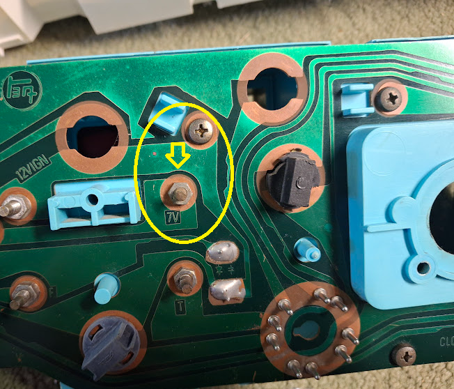
That is a strange one. Have you upgraded your headlights or the bulbs recently ! There is no headlight relay in the early Corollas. The headlight current passes through the contacts in the headlight switch on the column. I can only suggest that when the headlights are switched on, the +12V to the dash assembly drops off somewhat. The fuel guage is fed by a regulated voltage less than 12V, so that the guage always reads correctly. Are the headlights a bit dull also. I would measure the +12V at the steering column, with the headlights on & off, & see what the difference is. The regulator for the fuel guage can use a 7, 8, or even 10 volt regulator If the head lights are dropping the +12V supply to the dash, to less than 10 volts, that may be what is causing it.. My suggestion; is to have the headlight switch control an automotive relay only. Use the relay's contact to switch the +12V directly from the battery, via a 15A automotive fuse; to the headlights. P.S. Have a read of recent thread, which may help you shed some light on the issue. https://www.rollaclub.com/board/topic/85671-ke55-cluster-not-working-properly/#comment-738595 Cheers Banjo -
Sorry, I don't know the answer to that one, as I've never come across that previously. My KE30 2 door sedan; started life, with a 3 speed automatic gearbox; which shortly thereafter, got changed to a 5 speed manual gearbox. I never noticed that it made any difference to the speedo readings. My believe is that the speedo drive comes off the final shaft out of the gearbox; & the gear ratios have no affect on it at all. The only difference I can see making any difference to the speedo reading; is if the diff ratio has been changed, at some time; or larger wheels & tyres have been fitted. Wouldn't be hard to work out, how far out the speedo reading would be, if you knew the orgininal & replacing diff ratios. Gets a little bit more complicated, if you change wheel & tyres sizes, as well as the differential ratio. Others on here may have gone through this exercise, & may like to comment. Cheers Banjo P.S. I'm guessing You have removed the speedo cable; checked it for breaks or wear, & also the little nylon gear, that slides into the rear of the gearbox.
-
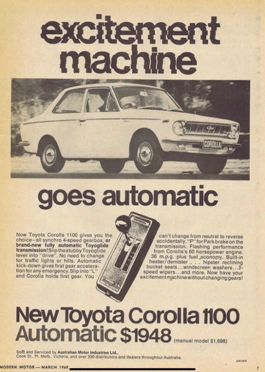
For those of You, who might find the advertisements small print a bit hard to read, I've typed it out, here below. Now Toyota Corolla 1100 gives you the choice- all synchro 4-speed gearbox, or brand-new fully automatic Toyoglide transmission ! Slip the stubby Toyoglide lever into "drive. No need to change for traffic lights or hills. Automatic kick-down gives first gear acceleration for any emergency. Slip into "L" and Corolla holds first gear. You can't change from neutral to reverse accidentally. "P" for Park brake on the transmission. Flashing performance from Corolla's 60 HP. 36 m.p.g. plus fuel economy. Built-in heater/ demister . . . hipster reclining bucket seats . . . windscreen washers . . . 2 speed wipers . . . and more. Now have your excitement machine without changing gears ! Cheers Banjo
-
Was cleaning up my computer, as I was fast running out of memory; & came across this olde advertistment in Modern Motor magazine, dated March 1968. The manual model was more expensive ! Cheers Banjo
-
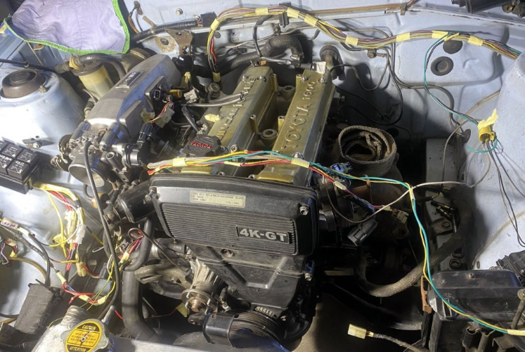
The head cleaned up nicely ! Still haven't quite worked out what the magnets are for, other than to actually attach the $3 360 degree protractor to the crankshaft pulley. Hope to hear that it fires up towards the end of this week. Will be really interested to learn what temperature the air gets up to down in the spark plug "valley" of the head, with the Mannon COP conversion mounting plate in place. Is there any way, a tube could be installed, that would naturally force O/S air through that well, & out the back end ? Cheers Banjo
-
Hi Neeka, With your added advice that it starts "sometimes", indicates it is either a simple wiring breakdown issue; or a start relay or issue with the starter motor itself. If it was me, I'dd attack the problem from both angles. (A) Remove the starter motor, & have it tested by an auto-electrician. The most common issue is that the starter carbon brushes have worn to the point, where one of them is barely making contact. An auto-electrician can also trim the commutator, to ensure it is perfectly "round" . Sometimes the brushes wear; to the point, where one has lost contact with the commutator. (B) The ignition switch wiring & plug & socket looks suspect, from your photos. That could well produce the intermittent, starting; that You are reporting. Even if You don't have a multimeter, a simple "trouble lamp" can let You see where the +12 volt power, is not getting through, when You turn the ignition key on; then to the start position. If you work it out yourself, you will be all the wiser, when it is final identified & fixed permanently. Good Luck; & let us know what You find. Cheers Banjo
-
It appears to me; from your photos, that it may be, that the ignition switch itself is OK, but the plug in connector & socket that connects the ignition switch to the car's wiring harness, is corroded & unserviceable. I may well be, that if you cut off the plug & socket, & substituted another generic plug & socket; or simply connected/soldered the wires together, without the plugs & sockets; then maybe the car will work perfectly. As You have the ignition switch out; You could test that the contacts inside the ignition switch connect OK, with a simple multimeter, or a battery & test light. Even if that is a temporary measure, to get you going again; it would then allow You time to search UK, French & German ebay sites, & see if anything comes up when looking for Neiman ignition barrels. Even if You can't connect it up, without the plugs & sockets; then any good auto electrician, should be able to do that for you, & get You mobile. Cheers Banjo
-
If You have ever played around or experimented with COPs. (Coil Over Plug), or have wondered how they all work; or why there are 3 wire & 4 wires ones; here is a link to a utube video, that is long, but is very informative. All You Need to Know about COPs I've played with & experimented with several different brands & types, & believe me; All COPs are not borne equal ! No ! That is not one of mine. some guy on the internet, who suffered this fate, & had to rethread the spark plug-hole in the head, without taking the head off. Cheers Banjo
-
Altezzaclub, mentioned the distributor cap. The HT voltage is produced by the HT center connection on your ignition coil. This is fed via a single HT lead to the center point of the distributor cap. Inside the distributor, the "rotor", points that HT voltage to the appropriate spark plug lead. However; inside the distributor cap, is a carbon brush that transfers the HT to the top of the rotor button. To keep that carbon button in contact with the rotor button, there is a very tiny light spring behind it, to keep the carbon bush in contact with the distributor rotor. These tiny springs are known to break, or burn out. It they break, it creates a second spark plug gap. I actually had one break years ago, & the engine actually went better, until I put a load on the engine, & it missed badly. Have a look & You just might have found your problem. https://www.rollaclub.com/board/topic/76154-high-energy-ignition-coils/#comment-721645 Cheers Banjo
-
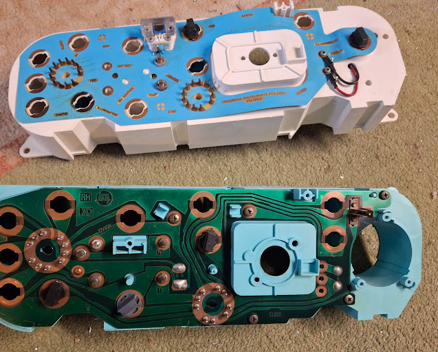
When You have the dash out, can You take a photo of the regulator itself; which is directly behind the post or the rear, of the dash; where it is labelled +10V. If the regulator looks discoloured or broken in some way, I would suggest replacing it with a solid state one. Once You have a +10V voltage there; with no load (fuel or temp guages) applied, You can then add one at a time, & see whether, the +10V supply voltage slumps or drops. Cheers Banjo
-
That is not good. Assuming your battery is fully charged, it might be a good idea, to disconnect the alternator, whilst trying to sort out this fuel & temp guage issues. Cheers Banjo
-
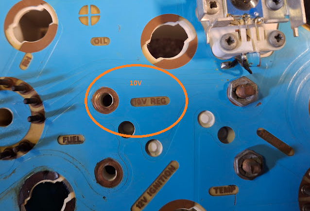
OK, If you are measuring +9V at the fuel tank, that is a good start. However, if the regulator is marked as being a +10V one; then the +9V reading, is a bit low. That could be your multimeter. Check it by starting your engine, & putting the multimeter DC volts leads across the car battery. If the battery is fully charged, & your alternator & regulator is working correctly, the voltage should read somewhere between 12v to 14.5V. If the reading of the battery voltage was OK, then we can assume the multimeter, is reading reasonably accurate. When you got a reading in the boot, on the wire from the dash; was the wire measured connected to the fuel level sender, or not ? If it was connected to the fuel level sender; did the fuel guage display any defection at all, of the indicating needle ? I would suggest that You fill up your tank to full, so you know what the level actually is, that the guage is suppose to be indicating. That's because it is a "bugger" of a job, to remove the tank, to extract the sender unit; so that you should make that your last resort, in trouble shooting. If your fuel guage is displaying some level, irrespective of whether it is correct, then it indicates there is no open circuit in the wiring. The level sensors, in the tank, do however, have a habit of wearing out after many years of use. If you get the +9V voltage at the disconnected wire in the boot, then that indicates, that possibly the fuel guage is in bad shape, & that maybe the +10V regulator has an issue. I would suggest, disconnecting the fuel sender wire, in the boot, above the tank; then measure the +10V terminal on the back of the dashboard. If is still reading +9V with no load, then the voltage regulator has an issue, as is most common. I might add, that while you are doing these tests, that you disconnect the coolant temperature sensor, near the bottom of the top water hose, in case it has an issue, & is loading up the +10V regulator. Sorry I cannot be any more specific, as there are a few variables in there. Basically disconnect the fuel guage & sendor, & the coolant temp sensor initially, & check whether that +9v reading, remains the same, or changes in some way. That may give me an idea, as to what is going on there. P.S. Unfortunately, that circuit that Altezzaclub posted does not indicate a +7 to +10V regulator at all. It depicts all the guages being connected to +12V battery supply, which is a bit strange. Maybe it's a very early circuit. However, your photo of the rear of your dashboard; indicates it should have a +10v regulator therein. Cheers Banjo
-
Good Morning ! Your picture indicates that the regulator in your particular dash unit, is a +10 volt model. The circuit for your fuel guage is very, very simple. When You turn on the ignition, the car batteries +12V is fed to the voltage regulator, which converts its output voltage to +10 volts. The reason there is a lower voltage, so that the fuel gauge's accuracy, is not affected by the +12V supply bouncing around, as it does. The first thing You should be measuring is not the resistance of the sender unit, in the fuel tank; but whether You have +10V at the so detailed terminal, on the back of the dash assembly. As I noted previously; it is the voltage regulators that are prone to fail, in these dashes. Turn the ignition on, & using your multimeter on a DC voltage range higher than 10 volts, measure the voltage between the terminal marked 10V, & chassis ground. There is a good chance the regulator has failed; & as result the fuel gauge will not read; even if it's resistance varies over the correct range. If you Google this subject, you'll find a number of articles & videos, regarding this issue. Here is one that may assist You. https://www.youtube.com/watch?v=Z7iRxnILM3U&t=28s I trust that assists. Cheers Banjo
-
Hi 79rolla, You have reposted your message of the 24th May, when myself & Altezzaclub, both replied, on that same day. Did those posts not assist You ? I only addressed the fuel guage & coolant temp issues, but You did ask about the speedo. Although olde Corollas can have speedo mechanisms in the dash; they do "wear out"; being mechanical. The issues you are seen could be caused by the speedo cable itself, that drives the speedo in the dash, via a flexible rotating cable, connected to the rear drive of the gearbox. This cable has very small "square sections" on each end of the cable. It is one of the mechanical items, that rarely receives any attention. My advice would be to remove the cable completely then remove the inner core & clean & reoil. Make sure the outer cable sheath, is undamaged, & has no kinks in it. In particular; take a look at the inner cables extreme ends. These are a small "square section", but can lose their square shape over the years. Let us know what You find; with pictures; if possible; as a photo can sometimes replace a hundred words. Cheers Banjo
-
The voltage regulator, will fix at least half your issues. The reason there is a voltage regulator, is that you don't want guages like fuel & temperature etc. tied to the +12V battery terminal voltage; which can vary a lot from cranking (7v-8V), to full on output of the alternator, whilst charging (14V - 15V). The voltage regulator for the gauge/s, is chosen as well below +12V. They are commonly 6V, 7V, or 8V. One real crude regulator I have here was a vibrating contact on the rear of the fuel gauge, & created an average voltage that was lower than the supply voltage of +12 volts. I even found one, that used a 10V regulator. The ones in the dash area, are usually nestled in between the various dash light bulbs; & often burn out, as they don't like things like fuel gage going short circuit to ground. Taking the dashboard out is a horrible job; (especially if You have big hands), but will be necessary if you are to fix or replace the regulator, If your dash wiring is printed circuit type, You will often find the voltage printed on the printed circuit plastic arrangement, adjacent to the regulator, which will often be "charred". I have repaired them in the past, with a standard LM7806 or LM7808 voltage regulator, available from places like Jaycar Electronics, & the like. When You get your dash out of the car; turn it over &, & take a picture of it, & post it here, & we'll see how bad it is, & suggest how it can be possibly be repaired. P.S. I do remember having the same issue as You; a long time ago, & modifying the dash panel as I mentioned above. It's been running for probably a decade, & I never had another issue. Maybe, I posted about it here somewhere ? I'll take a look. LINK: 2017 https://www.rollaclub.com/board/topic/73224-that-pesky-little-guage-voltage-regulator/#comment-708505 Cheers Banjo
-
Hi Keith, By TPS, are You referring to the throttle position sensor ? Maybe TPS refers to Trigger Position Sensor ? Once You post some pics of these items, you've sourced for your build, it will become a little clearer, & we can assist you. I'll have a look at Triggers Wheels, in the UK, if they have a website, & see if I can see what you've acquired. Trigger Wheels UK Cheers Banjo
-
Hmmm ! Does your setup, include a idle control valve, & is it being used ? When the engine is warmed up & idling; is the idling nice & steady ? The changeover of the ECU from idling to higher revs, seems to be where your issues appear. (as soon as you touch the throttle, & the TPS comes into play). I suspect that the O2 sensor output is probably not even used; in the idling control programming ? It may well be, that the older Haltech E6 series ECU You are using, is a bit too slow, at this point of the program. Have you recalibrated the TPS, recently ? Long while, since I used my olde Haltech EK6, so I cannot member any idiocies, I may have come across with it. It would do well, to put the timing light on the engine, & just see if there is anything unusual appearing to happen with the timing, at the point, where you, commence the throttle movement, when taking off from a standing start. There is an answer; so it is just a case of "seek & find", methinks ! Cheers Banjo
-
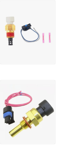
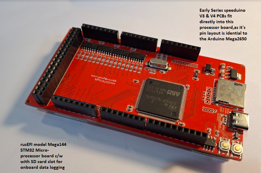
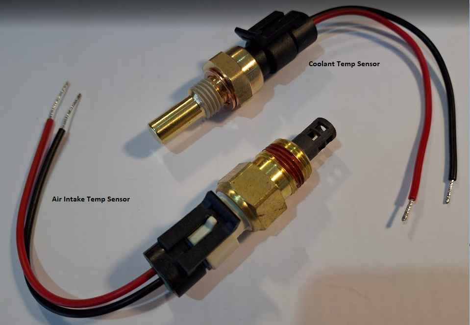
So a little bit more to do as yet, but very excited that my rusEFI Mega32 processor has arrived, & will soon be integrated into the Speeduino V4.3d PCB, in coming days. Most modern vehicles apparently now use 2 wire temp sensors for Air Intake Temp, & Coolant Temp; so no need for me to "gut" my olde sensorhousing that screwed into the thermostat housing. I managed to order them both; on ebay, from the same supplier, for a good price. Bargain; as they come with the 2 wire plug & tails also. They've arrived & I've checked them on Speeduino board, & they are reading spot on, at room temperatures. If I want them to be more accurate at their operating temperutues; it is simply a matter of holding them at that temp, & measuring their resistance; and then changing the voltage divider resistor on the PCB to match, so that at operating temperature the reading is approximately half the supply voltage (5V /2 = 2.5V) Cheers Banjo
-
Hi Alasdair ! Thanks so much for that wonderful set of photos. Only one sentence describes this . . . . "A work of Art & Dedication". Well done ! What colour have you decided upon, for outside. Matching the engine bay ? I take my hat off to You. Accomplishing body work, is not a great joyous part of working on any car; for me; so I really applaud your dedication. Now the fun part comes for me. The putting it all back together, & hearing that first roar to life, as You turn the key for the first time. Keep the photos coming. You provide inspiration to others. Cheers Banjo
-
Have a read through a thread on these matters going back about 8 years, in which I remember contributing. Gearbox Swaps I know mine was a bit of a nightmare, removing an auto & fitting a KE70 5 speed gearbox. It gets a mention in this thread. Apparently, the bearings for these older Corolla manual gearboxes are getting very hard to access these days, according to Altezzaclub. Hope that is of some assistance. Cheers Banjo


