Banjo
Regular Member
-
Joined
-
Last visited
Everything posted by Banjo
-
Love your dedication, at something, that takes a lot of time & patience; both of which You've got. Hat's off to You ! Cheers Banjo
-
Keep the photos coming ! We love photos. A photo tells a thousand words ! Cheers Banjo
-
Welcome aboard Foxxtrott ! I'll bet you didn't figure on getting such a detailed response, as Altezzaclub's advice; in such a short time. I found his advice excellent, & a good read; & wish a lot of that aftermarket suspension accessories, were available years ago, when everyone on this site (including me), were trying to improve their suspension setups, with swaps from other Toyota vehicles. You can still do that, if the professional kits, are outside your budget, but many of the swap items, are pretty rare to find at a wreckers these days. Good luck ! Cheers Banjo
-
Yep, You got it. Be very surprised, if it doesn't run significantly better, by just rotating the dissy a little bit anti-clockwise. Get yourself that timing light, & all will be revealed as you see the automatic rpm advance working dynamically. Keep us updated, with your progress ! Cheers Banjo
-
Hi Brayden, You've done well, & everything you do will help. The timing is out, as if anything; the red mark on the edge of the dissy, should line up with the other end of the brass arc, on the rotor button. The dissy rotor rotates clockwise, looking down from the top. If the engine is started, it will probably run, but as soon as you rev the engine up, & the auto advance kicks in, & causes the ignition, to spark, before the the brass arc on the button is near to the post inside the cap. This is where a timing light is so useful. You may be lucky, & it is only a case of simply unlocking the bolt into the block, that holds, & stops the dissy from rotating; & then turn the dissy a little anticlockwise. You can do this with the engine running, but it is probably safer to unbolt the clamp as it is in the picture, & rotate the dissy body, until the rotor is pointed towards the other end of the arc. Then get that timing light, & do it dynamically, at night; & you will see the whole auto advance function, in real-time. Let us know how You go. Clean the area around the crankshaft pulley TDC mark, & paint it with a little white out. It makes it so much easier to see. Cheers Banjo
-
Hi Brayden, The very first thing you should do, after you have manually turned the the crankshaft over, & have the timing marks lined up, on the crankshaft pulley & zero mark on the timing chain cover; is to lift the dissy cap, & see where the distributor rotor is pointing. If it is pointing towards the distributor cap post with the lead that goes to spark plug no: 4, then rotate the crankshaft another full turn, until the timing marks, line up again. The engine will then be in TDC No: 1 cylinder. Now look at where the arc on the brass tip of the rotor button, & see where it is, in relation to post in the dissy cap post, which is attached to No: 1 spark plug (the one at the front of the engine). We have seen distributors installed one tooth out, when it inserted into the block, to engage with the camshaft gear. We have seen them, where users have then rotated the dissy to get it to run, but when the car is running & the automatic advance kicks in, the rotor arm, will not line up on it's arc, to the post in the dissy cap, & the HV can't jump inside the cap, & you get miss firing. Where are You physically located ? I tried to look at the number plate in your picture of "Alice", but couldn't read it, at the angle the photo was taken. Cheers Banjo
-
Hi Brayden, Completely concur with Altezzaclub, that the timing light is your best investment, if trouble shooting or setting engine ignition timing. Visually, it allows you to check static timing, at "idle", and automatic advance, as a result in rpm increase at idle. You can also check advance under load, by removing the little rubber hose from the dissy, to the inlet manifold, & suck on it, to produce a vacuum, & watch the timing mark, move accordingly. The only advice I can suggest, is to completely clean around the timing marks on the timing chain cover, & the little "V" groove in the crankshaft pully, on the rear edge. Paint the grove with a little white paint of "White Out". The crankshaft pulley, can only be fitted in one position, as it has a single keyway. The only potential problem with the timing marks are; if some one has swapped a 3K or 4K crankshaft pulley, for one from a 5K engine, which has it's timing indent, is a different position; as are the timing marks on the 5K timing chain cover. Hope You get it sorted, as that is one beautiful Corolla ! Cheers Banjo

-
Hi Wil, Welcome aboard. That might be a big ask ! Any second had one, is probably going to have a short life, & a quick search on the net didn't come up with anything. If you can get hold of the original Toyota P/N, you might have some luck. Other than that, I can only suggest you look at current waggons with a "protective hosing", for taking wiring into the tailgate. A number of the VW models, including the Passat, appear to have a "wire protection hose", similar to the one in the KE70 waggon. Google Results Good luck ! Cheers Banjo
-
Hi Sam, I'm presuming the engine in the car is a 4K-C maybe ? I can't imagine the previous owner spending all that money on a 3K. The fuel cell, was a bit over the top, but from the pics, the twin carbies look like they have been installed OK. The real big thing, with fitting twin carbies; is whether anything has been done to the head's combustion chambers & inlet & outlet ports ? The K series heads, were never a good flowing head; as number one; they are not cross flow head; & number two; the head inlet & exhaust tracks, could well be improved. My personal opinion, is it's not going to greatly improve the engines performance, by simply fitting twin carbies, unless this is associated with some head work, to improve the air flow in, & exhaust out. However, unless you get that info from the previous owner, the only other way is to remove the head, & take a look. Any unknown engine, I always like to remove the head as a minimum first up; as it allows you to see first hand, what the state of the valves & their seats are; as well as the state of the bores, & whether there is any movement in the pistons. Again, not knowing what the state, the carbies are in, the first thing would be to remove them, & clean them completely, before trying to tune them. Tuning a single carby is hard enough, but twins can be a bugger, if you haven't got the experience & equipment to balance them etc. At a very minimum, before You do anything; I would warm the engine up; whip out all the spark plugs, & do a compression test. Even the colour of the spark plug electrodes, give a good indication, of how things are going, inside the cylinders. If you can find out some history of the motor, that would be a really good starting point. Cheers Banjo
-
Hi Sam, Glad You found the wire. Only other wire that I think that could be, would be a boot illumination light. However, if You already have a boot light, then it is very likely to be the fuel sender. (best drink that coffee, before it gets cold !) The fuel sender units inside the tank, are notorious, when old; for "wearing out"; as the constant rubbing can wear the fine resistance wire, they are wound with. They are seeming irreplaceable, unless you can find a wrecked Corolla, with a good one still fitted. I noticed you were lucky to have secured Historic Vehicle number plates with your new acquisition. Does that restrict You in Victoria, to only driving so many klms per month, or similar restrictions ? I was sent this email this morning for Heritage Plate auction, available here in Australia. Just have a look at some of the bids for these plates. Crazy ! https://collectingcars.com/collection/heritage-number-plates?utm_source=Email&utm_medium=email&utm_campaign=SF_CC_Collecting_Push_18/June/2024&utm_term=&utm_id=626394&sfmc_id=6149295 Cheers Banjo
-
Hi Sam, The wire at the fuel guage in the boot area, basically earths, on grounds through the variable resistor, which is the fuel level sender, in the tank. The guage responds only gradually (damped), so that it is not floating up & down, whilst the fuel is sloshing around in the tank. With the ignition on, have someone sit in the car & watch the fuel guage. A second person should take the wire you've found, & connect it temporarily to a part of the chassis, which is "bare" & clean. If the guage starts to rise, as observed by your helper, you've found the right wire. There shouldn't be any other spare wires in the boot area, if all the tail, stop, indicator & licence plate illumination lights are working. Only hiccup could be if a previous owner has rewired the car. Let's know how you go. Cheers Banjo
-
Hi Paul, I've just read Altezzaclub's comments to You, & realised, that your original question was It appears to me, that you are advising the the engine had lash-caps fitted, when You purchased it; but now after overhauling the engine, & decking block, & skimming head; You are now concerned as to whether the lash caps should be reinserted, as they may change the valve timing. I would guess, it would only be an issue, if the amount decked from the block; & skimmed from the head, is enough to change the valve timing considerably. As You've adjusted the bores slightly, to take the 30 thou O/S pistons, then that increase in swept cylinder volume, plus block decking & head skimming, would have increased the compression ratio. Have you calculated, or measured the cylinder head volume, to work out the resultant compression ratio after these mods ? Personally, from what you've advised, I don't think you would have changed the valve timing significantly. You don't say, that You have actually removed the Lash Caps, which I assume have a reasonable thickness in the top cap area. If you are really concerned, you could always fit a timing disk; remove the spark plugs; & with a dial guage on the valve spring top retainers, take note of the opening & closing angles of all valves. Personally, I wouldn't remove the Lash Caps. If the engine builder had originally fitted Lash Caps, I would leave them. From what I have read; when lash Caps are used, the lengths of the valve stems are shortened, to accommodate the extra thickness of the Lash Cap, so that valve timing is not significantly altered. Your engine builder, is your best guide to obtaining the correct answer to your query, but if you would like to pop a couple of "close up", pics, of the valve coils & rockers etc., it might give us a more informed detailed look, at your concern. Good Luck ! Cheers Banjo
-
Hi Paul, That Super 7 is beautiful, & I'm sure is a great performer with the 2TC, because the car is so light. You're making us very jealous ! Toyota red-lined the TC2 at 5500 rpm, from memory, but I'm sure the Fejer Brothers, would have modified the 2TC slightly, if they knew it would be used up to around 7000+ rpm. As I said in my original post, the Lash Caps are installed to put a wider area, in contact with the cam tip, or the roller; in the cam tip, if one is fitted. This is primarily done, to prevent damage, breakage or bending, of the Stellite valve stems. However, it maybe that the valves were replaced in your engine, at the time the Fejer Brothers produced these classics. Here is a link, that You may have already read. You will notice that their alloy low weight blue rockers, have rollers, but no "Lash Caps" from what I can see. You would assume then, that the valves were of a material, much better than the original Toyota valves. The 2TC engine was a fairly robust engine, for it's time in history, & some incredible HP was derived from them, especially, if a blower was added. We'd love to see a few pics, from under the hood. I imagine, the original build by the Fejer Brothers was fairly high class, & of very high standard ? Please keep in touch ! Cheers Banjo

-
Welcome Aboard Paul, Lash Caps are only really used of very high performance engines with roller rocker arms. They increase the area of the top of the valve stem, & prevent valve tips & rocker damage. https://www.yellowbullet.com/threads/lash-caps-do-you-guys-use-them.35874/ Cheers Banjo
-
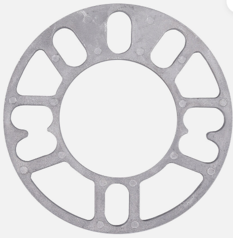
Hi Daniel, Welcome aboard ! Glad it worked out ! Did you use the simple thin ones, similar to below . . . . . . . . . or one of those thicker ones, that sometimes come complete with studs ? Cheers Banjo
-
Hi Sam, The easiest way to determine, which is which; is to disconnect the rubber hose on the LHS, in the photo, (which is probably the outgoing fuel line) & remove the whole assembly from the tank, by twisting it. This is easy in your situation, as the tank doesn't appear to be fitted to the car. Normally, in Corollas, with the tank vertically in the boot; You have to remove the tank altogether from the boot, to be able to withdraw the fuel pickup & fuel guage assembly, from the tank. Once removed, it will be clear, which is fuel out, return fuel in; & vent connections. Let's know how You go. Very neat & original under the bonnet, in your KE55, except for the twin carbies & the oversized battery. Someone has also paid close attention to "earthing", of engine , chassis, & battery, from what I can see; which is good ! Is that a little "insulator" flap over the top of the battery's +ve terminal, so that it does come in contact with the underside of the bonnet, on a rough road ? Altezzaclub on here, has always suggested moving the battery location to the opposite side of the engine, down under the coolant overflow bottle, which can be moved elsewhere. Getting the battery down low, close to the "chassis rail", lowers the "centre of gravity"; particularly, when the battery is larger & heavier than standard, as is yours. The only downside is a longer heavy cable is needed, to connect the starter motor, to the battery's +ve terminial. I think it is a good idea, but I just haven't got around to orgainising it, as yet. Cheers Banjo

-
PM sent to You. Cheers Banjo
-
Golf R ! https://www.carsales.com.au/editorial/details/faster-2024-volkswagen-golf-r-teased-144309/ Now if money was not a stumbling block; then a big Yes; but at $ 60K - $ 70K, that might hurt a bit. My son's girlfriend's, whole family are Volkswagen thru & thru, & swear by them. No one, including me, will put down Volkwagen's reputation for reliability. However, somewhere along the line, way back; pulling a kombi engine; & a Bettle engine out for friends, in a driveway, without the assistance of a vehicle hoist, still reminds me a stiff neck, for a week or so afterwards. My earliest initiation to Volkswagen, was in Papua New Guinea, where I worked for a while in my late teens & early 20's. I was on contract, but we had to find our own accommodation & transport, although we were paid an allowance. Finding good secondhand cars was an issue, & rust was a problem. I remember one FB Holden, where you watched the road beneath you fly by, below your feet, & that was whilst driving. In Rabaul in East New Britain, we came across, a fully imported German VW which was, I think; the most basic model they ever made. It had a 27HP engine, when I think the Australia model, was 30HP , at the time. It had the little oval window, at the rear, but it had had a divider in the middle, unlike the then current Australia model. It had no fuel gauge, but when you ran out whilst driving, you kicked a little lever, to the left of the clutch pedal, & the petrol then exited the fuel tank from a second lower pickup point, & got you home. However, for all the basics; it never broke down. I tell a lie ! Once we broke a fan belt, which is a pretty important item, in an air cooled engine. We didn't have one, but did use a girls panty hose, that had been left on the back seat, (duno how it got there) & we made it back to town. Cheers Banjo


-
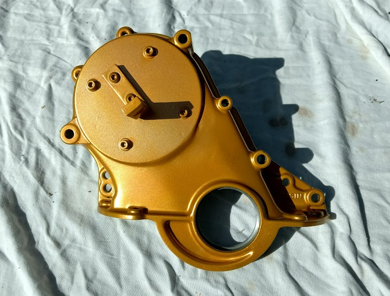
Sob ! Sob ! My 5K engine has just become obsolete ! Toyota To Introduce the INN Engine at 200HP per litre ! https://www.youtube.com/watch?v=rGXqA5EvSkI Meanwhile, I'll just get my 5K to be fully ECU & EFI controlled ! Just about to fit modified camshaft cover back on; & put it all back together. Cheers Banjo
-
Just love it, when a project comes to "fruition", & the road trips get going, under it's tyres ! Well done, & a good thread. I'm sure it will be appreciated by many, over the years on here. Congrats Cheers Banjo
-
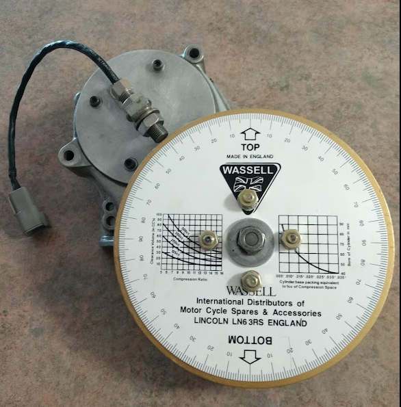
Got a bit side tracked there, with this camshaft sprocket chain advance / retard possibility, but will get back to that later. Most important thing is to get this "flying magnet trigger wheel" installed & running, with my Speeduino & Tuner Studio, on the 5K test bed engine. However, after finishing my 8mm thick "flying magnet" trigger wheel; I learnt a lesson, that I should have known; that "bigger is not always better". You see, I embedded 36 off 4mm dia. x 25mm lg. rare earth magnets in the disk, only to find when I tested it, that the Hall Effect sensor would not switch off. The magnet poles, facing out along the edge of the disk, were 17mm apart, on a radial edge, of the 200mm diameter aluminium disk; but the magnetic field strength was too strong, to allow the Hall Effect sensor to switch off. One of the reasons I used the 25mm long "rod" magnets, was because there was a large surface area, on the sides, which would provide a large area of Araldite adhesion of the magnets; to the inside of the 27mm deep holes in the aluminium disk. So back to using my olde 6mm thick 200mm dia. disk, with 36 off 4mm dia. x 6mm long rare earth magnets. Finished it today, & on the bench, it works perfectly. The trigger north pole, trigger reference magnet, is currently positioned at 270 degrees ATDC. So all I need to do now, is get the camshaft sprocket front engine cover, back on the engine, & do some serious testing, with the oscilloscope, with the engine running, & then the Speeduino. Cheers Banjo
-
Glad it worked for you ! Many of the aftermarket tachos, require an input signal, that is a 5V DC or 12V DC square wave, frequency signal. Unfortubately, when these after market tachos, are attached to a conventional CB ignition system, they don't like the large spike voltage, that appears at the negative terminal of the ignition coil, every time the primary current in the ignition coil collapses. There are a number of interface circuits & suggestions on the internet, to allow you to use the aftermarket tachos, with a conventional single coil CB ignition system. The reverse also happens, when a modern ECU is added to an older car, where the ECU tacho output is a 5V or 12V DC square wave variable frequency signal. This does have the large spike, which the original tacho in the older car, is expecting. Again, the internet provides a couple of fixes, to reintroduce the collapsing coil current spike, so the cars original tacho, can be utilised. Often this can be as simple as having the ECU tacho signal, switch a driver, that operates/switches on, an ordinary 12V automotive relay; whose collapse will still produce a spike, high enough, to trigger the older cars original tacho. Cheers Banjo
-
Hi Thomas, Welcome aboard, & plenty of people on here, that would be only too willing, to offer you advice, when necessary. If you are working to a budget, then I would suggest, that once you get the engine home; that You strip it gradually, & tag everything, so that when you put it back together; in months to come; & that everything is in plastic bags or bottles, clearly marked; particularly nuts & bolts. Once it is completely stripped, you will be physically able tp inspect things like bores & rings, & big end & main bearing slippers etc. If your 4K happens to be a 4K-U model, You will be in luck; as that variation of the 4K; put out more horsepower, than the regular 4K-C, which had a lot of California compliance gear on it. (hence the "C") Once you've inspected everything, you'll have a much better idea, of what needs to be done, as a minimum. Then if you budget allows, you can tackle other items like cam grind, performance valve strings, & maybe working the head. Greatest issue in trying to "get more power", from a K Series motor was the head design. Not being cross-flow doesn't help, but the intake & exhaust passages were pretty ordinary, & the engine can be made to perform much better, with port & polish, & removing lips etc, that reduce flow. My advice is, to take lots of photos, whilst you are stripping it down. K Series engines are getting pretty olde now, & it could be original, or it may have already had a reco, at sometime in it's life. You are about to find out. We look forward to hearing about the teardown, & seeing some pics, as you go. Cheers Banjo
-
Hi Si, That is a perfectly reasonable explanation, which is why I've tried tried to get hold of the installation instructions for what I believe is a CS9000 Rollamaster dual link K Series kit, that came with everything, including a new chain tensioner & guide. I've searched the internet, without any joy. Rollmaster I believe is a Queensland company originally, but looking at their website, they now seem to cater mostly, for USA V8 engines. A lot of chatter on the internet, indicates their instructions may be "confusing". My "mental block" is; that irrespective how far you move the camshaft sprocket in one direction or the other, it can only be in "full chain link increments". So moving the link on the crankshaft sprocket 1 tooth clockwise, is the same as moving the chain on the camshaft sprocket 2 teeth. However, the indexing of the pin that locates the front of the camshaft to the rear of the camshaft sprocket, is incremented in 12 degree camshaft degrees, whereas, leaving the pin in the original pin hole, & moving the chain one tooth on the camshaft sprocket only moves the timing 10 degrees. If the pin location on the back of the camshaft sprocket is a "vernier" adjustment, how can it be a vernier adjustment, when it moves 12 degrees, when the full link I've completely missed something here, but can't quite see, where I have got it wrong. Could it be thank you move the link 2 off camshaft sprocket teeth, being 20 camshaft degrees; then index it back, with the pin 12 camshaft degrees; resulting in an effective change of 8 camshaft degrees. That is still 16 crankshaft degrees. It's got to be something weird like this, but I'll never know, until I uncover the original instructions. The only basic instructions I could find; was here on RollaClub website, posted by Aidan in 2014. Apparently the instructions are different for most of the Rollmaster kits, because they are working with all different engine manufacturers, where one solution, does not fit all applications. Cheers Banjo
-
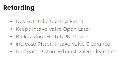
I had a close look at the RollMaster double link chain kit, I purchased a few years back, & fitted to my 5K test engine, to see how many degrees of crankshaft advance or retard, was possible, using the markings on the new Rollmaster camshaft sprocket, for mating with the location pin, on the end of the camshaft. i believe the Rollmaster kit I purchased was a model CS9000. Here is a thread on here from 13 years ago. https://www.rollaclub.com/board/topic/54177-rollmaster-cs9000-adjustable-timing-gear/ The camshaft sprocket has a total of 36 teeth around it. The crankshaft sprocket has 18 teeth on, it, as you would expect, as 36/18 equals 2; & it takes 2 revolutions of the crankshaft, for every single rotation, of the camshaft. To my way of thinking, we have always had the ability, to advance or retard the valve timing, in relation to the crankshaft; by simply moving the chain links one or two teeth, forward or backward. Thirty six teeth on the camshaft sprocket, means moving the chain one link in either direction, at assembly, would result in advancing or retarding the camshaft, in relation to the crankshaft position, by 10 degrees, of camshaft rotation. However, when we talk about advance & retard, it is relation to the crankshaft; one link movement (10 degrees) on the camshaft, equals 20 degrees of movement on the crankshaft. That is a big jump, which is probably why the pins position on the camshaft sprocket, is the preferred method of advancing or retarding the camshaft in relation to crankshaft position. However, there are just nine holes drilled into the end of the camshaft sprocket. They are not evenly spaced. There is room for 3 more, if required. If there was 12, then 360 degree of camshaft rotation, would mean 360/12, would be 30 degrees per pin position, movement/relocation. However, as we have to relate that back to crankshaft degrees, that would mean, that moving the camshaft location pin, one hole to the left or right, would be making a change of 60 degrees of crankshaft rotation. That is a very big change, for one pin setting repositioning either advance or retard. I'll have to do a bit more research, as I'm sure there is something wrong with my logic above. By changing the sprocket position, & changing the cam shaft position, You either make all the valves open & close later or earlier. However, the distributor's cam is also moved, & therefore the triggering point, in the cycle, of the spark plugs is also moved. Maybe you have to move the distributor rotationally, around 1 distributor tooth, to compensate, so the spark fires at pretty much the same original timing point, in the cycle. The K Series dissy's had 12 teeth on the bottom of them, Moving them one tooth would effectively be 60 degrees of crankshaft rotation. (360/12 = 30 x 2 = 60 cranks shaft degrees) That could be, while reading some of the other Rollmaster instructions; the final comment was, to check your ignition/distributor settings. So I'll have to see if I can't find some Rollmaster instructions on the net somewhere, that explains all this, as it would be a pain to get it wrong, & have to keep removing the camshaft sprocket cover, time & again. I went looking on the Net, but only found this little diagram so far, which is the original factory timing marks. Cheers Banjo