

Banjo
-
Posts
2028 -
Joined
-
Last visited
-
Days Won
98
Content Type
Profiles
Forums
Events
Gallery
Blogs
Everything posted by Banjo
-
Welcome aboard, & thank you for joining our community. Where are you physically located ? Many of our members are globally located, & wheels are going to be an expensive item, to freight, depending on where you are based. Cheers Banjo
-

Electrical Driven Water Pump on a K Series Engine.
Banjo replied to Banjo's topic in KExx Corolla Discussion
I found a DC motor speed controller on ebay, which controls the electric water pump, & flow of the coolant, from a trickle to full on. It handles a DC load of up to 10 amperes. With the radiator cap removed, you can clearly see the water flow change as the water pump speed is changed. It has a knob on it, which will be useful, as I manually try different flows & resultant temperatures, but also can be controlled by a 0-5V DC voltage, ultimately; from a controller, once a control system & program, is determined. So I started fitting sensors to the coolant system in several spots today. One on the hose leading to the top of the radiator, which will basically measure the temperature of coolant leaving the engine head, & entering the radiator. I already have a return line, at the back of the head, which returns hot coolant to the thermostat housing. I will fit one to that pipework, close to the rear exit from the head. Another will be fitted at the water pump, which is attached to the lower outlet from the raidator. This will allow easy delta T across the radiator, by sunbtracting radiator outlet temperature from radiator entry coolant temperature. The other place, I would like to measure coolant temperature, is inside the block coolant passages. The most convenient way to accomplish that, is to tap a temperature sensor, into a Welsh plug on the side of the block. It's simply a matter of drilling a hole & tapping it, in a Welsh plug, & then replacing an existing one. That will require the manifolds to be removed, to gain access to the three (3) off Welsh plugs on a K Series engine. So almost there, & should be soon starting the fun bit; which will be determining times & control program, to get the very best coolant temperature control. Cheers Banjo


-
What pars are used in KE2x (3k engine) driveshaft?
Banjo replied to Tomas's topic in KExx Corolla Discussion
Ah Uni Joints ! A very much unloved item, that gets little attention, because they are not readily accessible. Every time I have my car up on the ramps; I give them a wriggle & see if there is any unwanted movement. I've seen good mechanics, whenever they have a car up on the hoist for anything, including just a simple oil change, feel all the universal joints, whilst awaiting the oil to fully drain. Tomas; keep us posted, with your progress. Cheers Banjo -
Hi Jesse, Bear in mind that there is a colour code for all the wiring in your car, that can greatly assist, in tracing wires, when you are working blind, as You are, because You have no idea, what the previous owner did, which appears to be pretty drastic, in places. For example, in your picture above You are holding two" red" wires. One appears to have a "light blue" stripe; the other doesn't seem to have any colour stripe at all. If you look at the wiring diagram, at the area, of interest to you, which is the warning lamps & guages, you will notice that the power wire coming from the 10A fuse, to all guages & warning lights, is coloured Red with a Light Blue stripe. This should have +12V on it, if the fuse is OK, & the ignition is on. Just test every part of the circuit that way, with a test light, with the clip connected to a good earth. Take for example the Fuel Warning Lamp. according to the wiring diagram, it should have +12V power fed to it by a red wire with a light blue strip. The other side of this fuel warning lamp, should have a yellow wire with a light blue strip. This of course assumes that when Toyota manufactured these cable looms, they had all the colour coded wires available. I found to my horror years ago, when rewiring my KE30 Corolla, where a wire colour would change from one colour to another, from end to end. When I unwrapped the loom, I found a crimped join in the middle of the loom, where they ran out a particular colour, & substitued another colour. You will only solve the horrible wiring mess You have inherited, by systematically working through this, circuit by circuit. Hope this assists. Cheers Banjo

-
Which part of the KE70 car floor, is your photo of ? Cheers
-
Hi Jesse, That relay you referring to, is not a relay. Relays always have more than 2 wires to them. That is a flasher unit. It says so on the side. If it is connected to anything related to guages & warning lights, I can image it is causing issues. Maybe the previous owner was trying to make the "warning lights" blink. Who knows ! It wouldn't work ! There is usually not enough current from "pilot" lamps to drive the "in-line" flasher. Remove it, join the red & white wires togetherm, & see whether that is the issue. Forget about the fuel guage for the moment. The sender unit provides a ground or earth connection, through a variable resistor. Leave that till last. Once you got the rest working, I'll advise how to test the fuel guage. Fuel level sensors in the tank, are notorious for "playing up". Your best friend, in this kind of electrical fault finding scenario, is one of these. Have you got one of these ? This one is $6- $7 on ebay Cheers Banjo


-
Hi Jesse, The fact that You have +12 Volts at both those points, indicates that "the issue" is on the ground/earth side of the connections. Earlier model Corollas, pre your KE70; had a system where the power fed to the instruments like guages, was a DC voltage lower than 12 Volts. Usually, it was 7, 8, or 9 volts, off memory. The reason for this, was that the voltage in your car is never a constant 12 volts. The lower voltage was to ensure, that irrespective of what the battery voltage was, the guage had a fixed/steady voltage, so that it always read accurately. I'm presuming, that the instrument guages used in the KE70, have a small voltage regulator built in to each guage. In the older model Corollas, when this regulator burnt out, all the guages just stopped. However, your KE70 is wired differently. Before pull out the dash again, it would be a good idea to test the Park Brake, & Brake Warning lights. Both these switches just connect a ground or earth to their respective wires. The brake warning light, is probably a sensor in the brake master cylinder, to indicate when the fluid is getting low. Earth connections, in places like under the floor, or in the engine bay; often go open circuit, or high resistance, because of corrosion. Particularly, if the DC currents are very small, like milliamperes. Give all these earth connections a good clean. Cheers Banjo
-
Hi Jesse, I looked up a previous post of yours back in July, & I believe this 1982 KE70 with a 4K engine, is one that you indicated it had some "dodgy" wiring, which was the result of a previous owner. One of the problems with the "plastic" coated thin copper flat "printed circuit type" wiring on the back of the dash, is that it is extremely thin, & can burn out, & go open circuit. There is a fuse on your fuse box called "Guages", & this feeds 12 volt power to eight (8) items . . . . . No: 35 Braking Warning Lamp. No; 47 Low Fuel Warning Lamp. No: 59 Rear Licence Plate Lamp. No: 60 Parking Brake Warning Lamp. In addition, there are four (4) guages. No: 109 Oil Pressure Guage. No: 13 Fuel Guage. No: 185 Tachometer. No: 194 Water Temp Guage If any of these are working, then it indicates the 10A "guage fuse" is OK. However, I would check that it is actually a 10A fuse, & hasn't been substitued with a 15A, or 20A, fuse. If any of these items are working, then the non working items, will have an open circuit in the grounding side, which could be a switch, or an earth/ground track on the printed circuit plastic wiring. Only careful inspection visually, with a magnifying glass; or checking continuity with an "ohms" range, a multimeter, is going to determine where this fault lies. Let us know how You go. Just tackle it one item at a time, & when you find the fault, it may correct more than one item, that is not working. Bear in mind, that as this car has dodgy wiring, there may be more than one fault, you will have to find. Just start with say the rear licence plate, as that is the most likely place a short circuit, that could create an open ciruit, & stop other items from working, if it has burnt out the copper track on the back of the dash instrument cluster, which is a common circuit to more than one of the above listed 8 off items. Cheers Banjo.
-
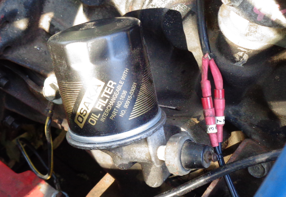
The Ryco Z68 is the most common oil filter that most 3K, 4K, & 5K engines use. On most cars the "canister" style screw-on filter is fitted with the threaded connection, is facing up. This results in the filter not being able to drain any oil out of the filter, after the engine is turned off. Unfortunately, on the K series engine, the filter is screwed in, with the threaded section at the bottom. Filters that drain, result in a slight delay, to oil pressure being fed to the bearings, when you first do a cold start. For that reason, it is more advisable to find a compatible oil filter, that has a non return & anti-drain / anti-siphoning valves built in. I found a Z68 compatible oil filter years ago, that has an anti-drain / anti-siphon valves built in, & was used in a Mercedes Benz engine. It's called a model Z423. There was a good discussion about oil filters & draining & siphoning, a few years ago here on RollaClub. Have a read of the following link. https://www.rollaclub.com/board/topic/73872-oil-filter-w-anti-siphon-no-such-thing/#comment-713701 I've used the Z68 & the stubby Osaka 90915 oil filters over the years, with no issues, but swear by the Z423 oil filter now, as you never get any rattles when doing a cold starts. Never rely on quantity of oil to be added to an empty engine, or after an oil & filter change. That is what a dipstick is for. With the car on level ground, fill & top up the engine, until it indicates full on the dipstick. Put the oil filler cap back on, & start the engine. Let it run for several minutes. Turn off the engine, & let the engine sit for several minutes, until all the "returning" oil runs back into the sump. Clean the dipstick, & reinsert & read again. It will usually, be just below the full mark. Top up until it reaches the full mark, & you are ready to go. Cheers Banjo


-
The basic, wiring for the ignition, starting, & alternator circuits is very simple. My suggestion, would be to forget about the original harness, & wiring, if it has been badly hacked; & just hook up a few tempory wires between dizzy / coil / & ballast resistor (if fitted). Then a simple push button between battery +ve & starter relay, & you should be able to get the engine to run. If you have a carby, with a electric valve on it, you will need to supply power (+ve 12V) to it also. Once you have the engine running, you could maybe introduce the original wiring back into the system, until the engine won't start or run, then you'll be able to repair the wiring concerned. Other ancillary circuits in the engine bay, like lighting, horns, & temp & oil press sensors are easy to add. I once completely rewired my engine bay, by cutting the main harness, where it comes through the firewall, from under the dash. Tedious, & time consuming, but a great result. Cheers Banjo
-
Electrical Driven Water Pump on a K Series Engine.
Banjo replied to Banjo's topic in KExx Corolla Discussion
Well, another milestone passed in this little experiment today; with the whole system piped up. I removed the thermostat altogether, so there was no impedance to the water flow, & then filled the system up with water. I then let the pump run, at full speed, with radiator cap removed; so any air bubbles inside the block, could be removed from the system. Only took about 30 seconds for all the trapped air bubbles to be removed. Looking down into the radiator top tank, with the cap removed; indicated the water flow was substantially greater, than the flow with the original "mechanical" water pump. It seemed funny, watching the water flowing through the system, when the engine was not even running. This however, will now be possible, when the engine stops on a hot day, & as well as the electric radiator fan running on; so will the water pump. This should result in both electric fan, & electric water pump, shutting down sooner. So next job is to build a pulsed speed controller to control the pump, between 12% - 93% capacity. I believe if the PWM speed control signal is removed altogether, then the pump will run at 100% capacity. Then I'll fit several coolant temperature sensors around the coolant system. I'll then fire the engine up, & experiment with a few different pump & fan control strategies, until it becomes obvious, which provides with the best results. There will be three (3) phases, to address. Startup, & getting up to temperature as quickly as possible. Running under load; & cool-down, after engine has been shut down, after being driven. Should be a lot of fun, & I'll pass on here, to anyone interested; what those results are. Cheers Banjo


-
Nice work Geoff ! I can see your confidence building, & that You enjoy both "the journey", as well as enjoying the "end result". I look forward to your future efforts. Cheers Banjo
-
Found this guy on the web, who got two (2) engines, in the back of his hatchback ! Cheers Banjo

-
I'm sorry, but I just have to ask this question ! How the hell did you lift & place the 2 litre twin cam 20V in the rear of the waggon ? i'm presuming your answer will be . . . . "With Great Difficulty". Cheers Banjo
-
Electrical Driven Water Pump on a K Series Engine.
Banjo replied to Banjo's topic in KExx Corolla Discussion
I started off this thread, by enquiriing whether they knew anyone on here, or elsewhere; who had done the mechanical to electrical water pump conversion. I've trolled the internet, & there are a couple. https://www.youtube.com/watch?v=gX2A9rSLAPw&list=RDCMUCqvXGJXKeLCm6zg-JagDdzQ&index=1 https://www.youtube.com/watch?v=wJNqEZQKwpI https://www.youtube.com/watch?v=SWkCHaAAerM Admittedly, it's on a Mini engine, but the techniques & requirements are similar. Here is another commonly available electric water pump, off an early Toyota Prius. I like the fact, that it has three (3) rubber isolated mounting points, which renders it easily to mount; unlike the Bosch unit, I currently using. https://www.youtube.com/watch?v=1ojNID2jDz4 Cheers Banjo
-
Electrical Driven Water Pump on a K Series Engine.
Banjo replied to Banjo's topic in KExx Corolla Discussion
Got the pump lashed up on the test bed engine, & it is now going great, but was not without, a few learning curved balls encountered.. That's it; down in the lower LH corner of the pic. First thing I noticed, was how quiet the electric water pump was. In fact it was so quiet, it was hard to tell, it was running. The exercise today, was just to get it running On/Off, at full speed. Varibable speed; controlling the flow rate, will have to wait, until I build a suitable controller. Initially, I could not get the electric water pump, to run for more than a few seconds, before it automatically shut down. I figured it was sensing that the pump was "dry", & shutting down to protect it. It did seem however, a very short time, before it shut down. I have no idea, what sensor it uses, & was not going to pull the pump apart, to find out. Purging air from the coolant passages, may be a very definite requirement, when first filling the coolant system. I learnt a quick lesson, that the pump needs a "flooded inlet", at all times, & that the outlet, must be facing upwards, & be higher than the inlet; so no air gets trapped inside the pump body, at all. After I repositioned the pump, (as above) it ran without cutting out at all. I measured the DC amperes, & it was pulling 5.6 amperes. I haven't done a flow test on it as yet, as I haven't got it flowing through the block as yet. Currently, it is just lashed up, so that it pumps the coolant back to to the radiator header tank. The main requirement is, that the inlet of the pump, is at least level, or below, the bottom radiator outlet., as above. The pump is quite small, & will fit down in that area easily, on most vehicles. However, watching the coolant flow rate, through the top of the radiator, with cap removed; it certainly is flowing faster, than the normal mechanical pump, at about 2000 RPM. So next exercise is to feed it through the block & head, without, the thermostat in situ, & see what back pressure that places on the pump. & what the maximum flow rate, that can be achieved. I'll just collect what it can pump, in a minute; then multiple that by 60, to get the number of litres per hour. So now I've proved it works, next stage is to remove all the lash-up, & make it permanent, then repeat the exercise, with the coolant passing through the block & head. After that, it will be time to fit a number of coolant temperature sensors, all around the coolant system, so I can see the temperature gradient, between the top & bottom of the radiator core, & at various points inbetween. Cheers Banjo
-
The running out of fuel, when there is still fuel in the tank, is suggesting to me; that there is a crack or break in the pickup pipe, between the top of the fuel tank, & the bottom pick up point. Once the fuel gets down a bit, the break in the pipe, partway down, gets exposed, & sucks in air. I'm afraid, it's time for the tank to come out, for a complete inspection & clean. You cannot do any thing inside the tank, or even remove the pick up assembly; unless the tank is removed. While it is out, make sure you check the fuel sender unit. Cheers Banjo
-
Electrical Driven Water Pump on a K Series Engine.
Banjo replied to Banjo's topic in KExx Corolla Discussion
For those of you interested, here are the specs, of the Bosch electric water pump, which I will receive on Monday. I'm sure it will do the job. I had a giggle regarding the spec. for max. lift, of up to 7 metres. My guess is that the vertical distance from the radiator outlet, to the top of the 5K head would be about 1 metre, so no issues there.


-
I looked up the Goss G305A, & it is suited for the K series engine. I thought you'd probably fitted an electric fuel pump; hence the query about it "rattling", which is how an electric pump sounds, with no fuel flowing through them. The standard K Series mechanical fuel pump, is not mounted on a bracket; but bolted to the front of the block, & must have the isolation spacer fitted, so the lever arm, sits at this right point on the camshaft load. The replacement fuel pumps are not usually supplied with this fibre spacer. Please confirm, you have the spacer fitted, or send us a close up pic of the fuel pump, attached to the engine block. Cheers Banjo
-
Electrical Driven Water Pump on a K Series Engine.
Banjo replied to Banjo's topic in KExx Corolla Discussion
Hi Pete, With totally variable speed water pump, & complete control over the operation of the radiator fan, I can see how it should be possible to hold coolant temperature at a fixed temperature, or over a very narrow band; under all driving conditions. The electric water pump speed, will not be in anyway, controlled by the thermostat. In fact, I am hoping to remove the thermostat altogether, as both a restriction, & coolant temp controlling device. My preference would be to control & maintain, the coolant temperature, by electric water pump speed, & therefore, coolant flow rate; based on various inputs, into an intelligent controller. The electric water pump's on/off & variable speed operation, would be determined by a number of temperature sensors, located at different areas of the engine & block. I should be able to drill & tap sensors into the Welsh plugs, so I can see what coolant temp differentials are around the block. Ambient temperature would be an input, as well as whether the cabin heater was being utilised, as well as engine loading & operating characteristics, like TPS, RPM & MAP readings, many of which I can exported from the Speeduino ECU. The radiator electic fan, will also be on/off controlled by this intelligent controller. Coolant initial heating; & cool off, after engine stops; should also be a great improvement. My initial thoughts are, that during start-up; neither the radiator fan, nor the electric water pump, would run, for some fixed time (eg: say 2-5 mins); timing being based on ambient temperature. After that time, the water pump would run at low speed, so that there is some minimum flow of coolant, so all temp sensors, around the coolant track, can provide meaningful readings, that will be used for all control actions, thereafter. These are all unknowns at present, but that is the aim of the exercise; to find the best possible solution. I already have a bypass from the back of the head of my 5K engine, back to the lower side of the existing thermostat. There was always a short rubber hose bypass in the coolant system, between the existing thermostat housing, & the olde mechanical water pump inlet. I will retain this, but place a cock in it, so I can throttle it off, or even shut it closed, to see what effects it has. One of the aims & purpose of the exercise, to to reduce, or hopefully remove; the high temps of the coolant at the rear of the head & block, where flows are low, resulting in higher coolant temps. My tests have shown that the coolant temps around cylinders no: 4, can be 15 deg C higher, than those around cylinder no: 1. Many off us, who have lost rings or pistons, in our K Series engines, will atest, to it almost always; being cylinder 4 or 3. Early attemps to improve the coolant flow around cylinders 3 & 4, was the creation of head gaskets, where the coolant flow holes, between block & head, were sealed off, around cylinders 1 & 2; in an effort to force flow to the back of the block; & hence up into the head around cylinders 3 & 4. This worked to some extent, but also restricted total flow somewhat. I'm hoping to be able to open up all the coolant passages in the head gasket, between block & head. So, I going into this with an open mind, & not having all the answers; but sure that with what I come up with, will be substantially better, than what I have got at present. Soooo, Fun days coming up ! Cheers Banjo Cheers Banjo -
Electrical Driven Water Pump on a K Series Engine.
Banjo replied to Banjo's topic in KExx Corolla Discussion
Hi Sebastian, Yes, it's fun, cheap, & they were a damn good engine design in the first place; confirmed by their longevity. Once you've got your car body rust all sorted; You too, will have fun, I'm sure, with the mechanical side of things. Cheers Banjo -
Electrical Driven Water Pump on a K Series Engine.
Banjo replied to Banjo's topic in KExx Corolla Discussion
Well, a little bit further advanced on this experiment. The original water pump backing plate, cut down; is now mounted on the 5K EFI project. Without the water pump & it's fan belt driven pulley, I have fitted a shorter belt between the crankshaft pulley & the new 120A alternator. The belt adjustment tension bar, is now pivoted off a post on the upper RH corner of the backing plate; as previously, it was in the same position, but on the front of the pump body, that no longer exists. There is not a lot of room, betwwen the back of the alternator & the timing chain cover, so the white plastic pipe, was used to work out where an entry point was needed on the backing plate to feed the water into the block's water jacket. The original hole in the backing plate was filled in, & welded with a filler piece. A new hole was cut above to be the entry point for coolant to the block water jacket. The bottom raditor outlet, will be connected to an electric water pump, whose outlet will be connected to the bottom of this depicted 25mm dia. copper pipe. So here is what it looks like at the moment. The vertical copper pipe has been left intentionally long; so that when the electric water pump arrives from Sydney (thank you ebay), I can mount it down near the bottom radiator outlet, & then cut the depicted vertical copper pipe to a length, to suit the final position, of the new electric water pump. The pump I have ordered is a Bosch model, which they claim can move about 2400 litres/Hr. It is a 12 V DC 90W model, which means it will draw around 7.5 amperes, at full speed. It has an "S" terminal on it, where a frequency controlled pulse voltage can be fed in, with a frequency betweem 9Hz - 110Hz; controlling the pump from zero to full speed. I am hopefull, that once I have it working, that we can not only optimally control the coolant temperature, but make it more uniform across the block & head. Standard K Series motors, are known to run hotter on the rear cylinders; particularly no: 4. Cheers Banjo


-
OK, 1. What is the model of the OEM Bosch fuel pump ? 2. Where is this Bosch fuel pump mounted ? Up near the motor, or in the boot or rear of the car, near the fuel tank ? 3. Is the fuel pump making a rattling noise, as they usually do, when they are empty or dry ? 4. Are you using the original fuel lines in the KE-70, or has the previous owner modified that aspect also ? 5. Have you tried a small 5 litre can of fuel, on a stepladder, next to the car, higher than the engine; with a plastic tube gravity feeding fuel to your Weber carby ? Once you know that the engine runs OK, with an alternative fuel supply, in a can; then it is time to work backwards from the carby, testing fuel lines for leaks etc. However, if the KE70 has been standing idle for a long while, it maybe more fruitful, if you start at the fuel tank & pickuo, if your suspicions are right about the rubbish in the tank. Let us know what you find. Cheers Banjo
-
Really good that You have a grand father, with lots of Toyota experience. Olde engines can have lots of issues, that are hidden, that may not completely prevent them from running; but create conditions, in which they don't run well, at all. Common is one cylinder, that is "not pulling it's weight", due to burnt or pitted valve seats. Rocker arms, with grooves in them where they contact the valve ends. Cracked or soft valve spring/s. One cylinder with poor compression. The list goes on. If it was me, I'd be running the engine up to temp, then whipping all the spark plugs out, taking note of which spark plug was installed in each cylinder; & doing a compression check. Even checking the colour of the insulator inside the spark plug, can indicate a cylinder not combusting well. Next would be checking all the valve clearances, although as you have the rocker cover off; it would also be a good idea to remove the rocker gear, & check the sliding face of the rocker arm, where it comes in contact with the valve end. The carby could well need a complete clean & overhaul, but unless you can achieve reliable fuel supplyto it; it cannot be tuned. I still believe you may well have a minute leak in the fuel line, that is compromising the pressure at the carby. Disconnect the fuel line at each end. Blow pressured air though it in both directions, & see in any rubbish or rust comes out. Block one end, & feed air pressure at the other end. Check the line & any rubber joiners for leaks, via hearing, but to be sure, spray the outside of the line with water, & look for little bubbles, created by escaping air. I gather you have fitted a new pump, so we can eliminate that. It's attention to all these small details, that will turn up, what your engine's problem, really is. Don't lose sight of the fact, that it might not be just one fault, that is contributing to your woes. In olde cars, it can often be a couple of issues. eg: Have you removed the air filter, & guaged whether the engine runs better with or without the filter ? It will be something quite small; but you can only find it, by methodically working through each of the above. Let us know how you go. Cheers Banjo
-
Even if your car is parked on a hill, when you turn off the engine, there will be fuel in the carburetor bowl, which will be enough; to at least start it, next day. If you have fitted a new fuel pump, then the problem. is either in the fuel line, or in the pickup or pipework in the fuel tank itself. My first suggest would be to remove the inlet line to the fuel pump, & blow back down the line, to the tank. Get a mate to listen at the fuel filler hole, with the cap off, & he/she should hear the air bubbles in the tank. If good, that means it is not entirely blocked. It could still have a leak somewhere, where the mechanical fuel pump cannot pull fuel through, even though the pump is new. It's easier for the pump to suck air than fuel. Next step, is to get under the car & inspect the fuel line in detail. Look for damp patches. Check any rubber joiners, which are often old, hard dry, & cracked. Replace ! If still no joy, then it will be time to remove the fuel tank, from the boot, & take out the pick-up stork, complete with the fuel guage sender. I'm presuming you have taken the top of the carby, & checked that the needle & seat, plus float, are all working OK. If the car has been sitting for a long time, & the fuel has been sitting or evaporated, it can often leave a whitish looking residue on any part in contact with the fuel, which has since evaporated. Let us know how you go. Cheers Banjo


