

Banjo
-
Posts
1892 -
Joined
-
Last visited
-
Days Won
95
Content Type
Profiles
Forums
Events
Gallery
Blogs
Everything posted by Banjo
-
I found another one in my garage, & had a quick look. I stand corrected. It does not have a phosphor bronze pivot sleeve bearing in it. It has two (2) tapered nylon bushes, one at each end. New bushes are about $ 30 a pair on ebay. I did however confirm, that the idler arm bracket, fits all models from KE-30, through to KE-55. Unfortunately, the idler arm ball joint is not replaceable, & if the ball joint has failed, you need to replace the complete pitman arm, which incorporates the ball joint. Both items; complete idler arm assembly, & the pitman arm, are available on ebay. Cheapest I saw the complete idler arm assembly was about $ 60.00. The pitman arm, including ball joint, was about $ 40 - $ 52, so on that basis, it would be wise just to pay the extra dollars, & obtain the full new assembly, & get everything. Cheers Banjo

-

So Who is Going to do the First KE Rolla EV Conversion ?
Banjo replied to Banjo's topic in KExx Corolla Discussion
Lovely story about the very early (60-70 years ago) EV conversions, on the ABC website, yesterday. Good read ! https://www.abc.net.au/news/science/2023-02-04/worlds-first-electric-porsche-forgotten-history-evs-melbourne/101891670 However, it was a side story about a guy in Chinchilla, in Qld., that caught my eye. He converted a Dato 1200 ute. I worked for a company that had one of those once, & the ute cabin was hard to squeeze into. We can't let the Dato communitity, be the first ! Sure there must be someone out there, considering, doing an "EV", on their Rolla. https://www.abc.net.au/news/science/2021-10-18/converting-classic-cars-to-electric-vehicles/100533104 Cheers Banjo -
I had a look in my heap of spares, & I do have an idler arm pivot assembly, out of a KE55. I can't imagine, Toyota changed that much throughout the KE30-35-55 series. I was going to compare it, with my KE30 2 door coupe one today, but it was raining, so couldn't put my KE30 up on the ramps, to take a look. If it's fine tomorrow, I'll take a look. This one is missing the phosphor bronze bush in the middle. I'll take a look through my heap of bits tomorrow, & see if it is there somewhere; or maybe I've used it previously, but can't recall.


-
I have never come across a "crushed" bush on an idler, on any of my Rollas. All the ones I've seen have two tapered half bushes. The only reason I could imagine, they placed a crushed idler bush, would be, that it assisted "self centering" of the steering. That would require, I presume; that the nut be tightened up, on the crush tube, with the steering in the straight ahead alignment. It might be easier to just get a whole new idler arm assembly, with the two tapered, removable & replaceable bushes, & dice the crush tubed version altogether. Cheers Banjo
-
Hi Geoff, If your KE26 idler arm pivot, is the same as those in the KE30 series, I have never come across them "locking up". The bushes in these take a beating, & I replaced them every 4-5 years. I guess, that if the nut on the top of the pivot, was too tight, it might not turn easily & could appear "locked". By all means, back the nut off, until it turns, but don't leave it loose. Cheers Banjo
-
So the trigger wheel/disc, with magnets, & it’s decoder, is now running the engine, by firing four (4) off COPs sequentially; albeit, at a fixed advance of 10-12 degrees BTDC. (as per pics in the previous post) Next step to build an advance / retard controller. I built my ignition controller, with a “mapped” advance retard curve, by revisiting a tried & proven programmable ignition system, designed by Silicon Chip magazine, way back in March 2007. I say proven; as I have been using it in my KE30 2 door coupe, on a 4K-U engine, for years; with an Accuspark 3K dizzy Hall Sensor setup; & never had to touch it since, after I initially getting the advance mapping correct. I looked on the Silicon Chip website on-line store, & they still had the programmed PIC micro-processor for this project. I have built it up, in recent days, & tested it on the bench, & it appears to work well. The programmable ignition controller, can accommodate 2 off 11 x 11 advance/retard maps, (for duel fuel applications) or a single 15 x 15 map, which is what I’ve used There is no software, that communicates with this system, so a little hand controller, with an LCD display & some push buttons, is used to create the map. It’s a bit laborious, but works well. I used Excel to create the map. The MAP is a "little flat", to start with, but can be changed, during load testing, to optimise the advance setting, for various RPM & load ranges. I also limited the maximum RPM range, as my test trigger disc, & speed controlled electric motor on my bench, is not balanced; & the motor is only capable of 3500 RPM maximum. Once I get it on the engine & do some fine tuning, of the advance/retard map, I will be setting the advance as high as practically possible, without introducing “knock”, which could “spoil the party”. Not wanting to do that, I’ve yesterday built a Knock sensor kit; again put out by Silicon Chip in June 2007. (Silicon Chip still had the PCB in stock) Knock is caused by detonation, or too much advance; or high engine temps; or lower fuel octane rating, than normally being used; & results in mechanical piston rattle within the cylinder, around TDC. Modern cars all have a knock sensor, on the engine, that detects this piston rattle, & tells the ECU to back off the advance a bit. Apparently, all “knocking” in engines, creates “noise/knocks” in a frequency band width of between 4.5kHz & 6.5 kHz. The knock sensor itself, is basically a tiny microphone, listening to your engine. They typically use a piezo-electric sensor, which is attached to the engine block or head. The “knock or detonation” sensor controller, is basically a “notch” filter that only looks at frequencies between 4.8 – 6.4 kHz. When detonation, or knock is detected; a signal is sent to the ignition controller. As knock only occurs around TDC, the controller only looks at the knock sensor output, around TDC & for several milliseconds after firing has taken place. That avoids any other engine noise, that gets picked up by the “knock sensor”. The controller then automatically reduces the advance, between 0.5 to 6.0 degrees of advance, depending on the severity of the knock. I could nip down to a wreckers, & pick up a knock sensor, but I notice they are not that expensive on ebay, ranging from around $ 20 upto about $ 80.00. I prefer the screw-in type, rather than a bracket on the engine; as the sensor, then becomes part & parcel of the engine, & integral, to the block or head. Next question is where to mount it. My research indicates, that the preferred position is on the head some where. Has anyone out there ever fitted a knock sensor to their K Series engine, & if so, where did you attach it ? My personal preference, would be to fit it, high on the engine block, on the opposite side of the engine, to the exhaust header. I found a couple of threaded holes, behind the mechanical fuel pump, that appear to be roughly between cylinders 1 & 2. A bit tight in there, as the mechanical fuel pump obstructs; but I’m using an electric pump, & that area, has a blanking plate. Would welcome any suggestions. Cheers Banjo


-
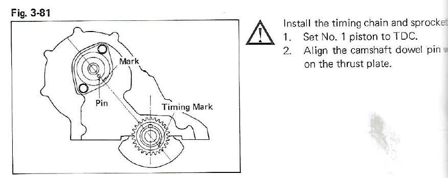
Hi Mate ! What model 4K engine have you got. Is it a 4K-C or a 4K-U ? As you have advised that the 4K is "fully worked", I'm presuming the camshaft has been reprofiled ? Is this the same camshaft that was in the engine, before you had the crankshaft ground & new bearing presumanbly; or did you have the camshaft profiled or a new one fitted fitted at the same time ? We had someone else on here recently, with camshaft tiiming issues. I'll dig out the thread & link it here, & you can have a read, & see if the info therein, is relevant to your situation. Here is some it below . . . . . . I've been trying to find You a pdf version, on the web; of the "Yellow Bible", which the Toyota factory manual produced for the K Series engine. I have a hard copy which I purchased years ago. I covers every K series engine from the 2K to the 5K-C. I have just scanned the picture that is most relevant to your issue. When a manual refers to things like assembling & dissembling a car engine, they assume the engine is out of the car on a bench. There is a difference between the word "vertically", & "perpendicular." The K series engine block has the top of the block (where the head bolts on), & the bottom of the block (where the sump bolts on) being perfectly parallel to each other So when the block is on a bench being assembled etc. the keyway on the crankshaft is both vertical & perpendicular, assuming the bench top is level. However, when the K series is installed in the engine bay, it tilts over to the LHS, when you are standing in front of the grill, looking into the engine bay. I've never measured it, but it looks roughly about 15 degrees. You are looking at the keyway, & saying it is 20 degs out; or off the perpendicular, but your engine is in the car & already tilted, to the LHS. Your reference plane should be the bottom edge of the timing chain cover, which as the diagram above indicates, is exactly 90 degrees to a line drawn vertically through the crankshaft keyway. I don't know how else to describe it to you. Probably the best I can do, is show you a picture on Rollaclub, I took about 4 odd years ago, where someone else, had a similar issue to that which you have. Notice the engine is sitting on wooden blocks, supporting the engine on the block flanges where the sump is attached. Note the crankshaft keyway, is both vertical & perpendicular. If you want to read that post, then go to this link. https://www.rollaclub.com/board/topic/74223-worked-5k-problems-on-1st-start/ In conclusion, I don't believe that your engine needs to get pulled out. I believe the "timing error" you are seeing with the timing light, is caused by something else; probably vacuum problems. To stop any vacuum issues, causing timing errors, simply pull off the vaccum hose from the dizzy, so it cannot affect the advance at all. However, you must block the hose off, & any other offrices into the inlet manifold, so that the engine has a chance of getting the right air / fuel ratio. I hope this assists. Cheers Banjo

- 1 reply
-
- 1
-

-
These have arrived now, & I've tested them all for dwell time required to reach full coil load amps. I'm not sure whether these Denso COPs, I've purchased are genuine or copies. However, whatever they are; their dwell times are all identical, as they must/should be. The trigger wheel, dscribed in this thread, & it's associated decoding electronics, was fitted to the 5K test engine stand over the weekend, & it is all working perfectly, albeit, with a static 10-12 degrees of advance. I had the use my little CPS (camshaft position sensor), instead of the one I had incorporated into the camshaft spocket/chain cover. It was in the wrong position, so it was easier to use the other CPS sensor, built into an old cut down 3K dissy, as it can accomodate & place the camshaft position pulse, anywhere in the 720 deg cranshaft 2 revoloution cycle. Just now building a proven circuit, for providing a load & advance map for RPM & Load compensation. I also intend to add a knock sensor to it, so that I can take advance to it's limits without any chance of serious engine damage. One of the disadvantages of using a COP; is that there are no longer any spark plug leads, to put the strobe timing light pickup onto. Note my "workaround", by mounting no: 1 cylinder COP, upside down, & running a spark plug lead between the spark plug & the bottom tip of the COP. I have seen a tester on the internet, & I belive you can buy them commercially, that senses whether a COP is firing, by just placing a "wand" on the top of the COP itself. I should be able to build a "wand" that could then be used to trigger the timing light, so that the above worK-a-round, is not required/needed. Cheers Banjo


-
So Who is Going to do the First KE Rolla EV Conversion ?
Banjo replied to Banjo's topic in KExx Corolla Discussion
Oh I love it ! The love affair continues. You lift the bonnet, of your EV powered car, but still has all the appearances of a worked V8. I think it is call "holding on"; to what we stiil love & are so used to. https://www.sparesbox.com.au/blog/electric-gt-ecrate-motor Cheers Banjo
-
Every millisecond is important, when it comes to timing & charging a coil primary winding, whether it be a single coil system, or a COP system, with one coil per cylinder. Lets look at the maths of ignition timing. In a 4 cylinder engine, with a points/distributor based system, the dwell angle (period during which the points are closed & the coil primary winding is charging), is pretty common, at around 45 degrees; depending on the lobe profile on any given distributor. So if we relate that to crankshaft degrees, it would be 90 degrees, as the distributor only runs at half crankshaft speed. 90 degrees equals exactly 1/4 of a revolution of the crankshaft. If the engine is at idle at 1000 RPM, then one revolution of the crankshaft takes 60,000 milliseconds, (millisec in a minute) divided by 1000, & equals 60 milliseconds. As 90 crankshaft dwell angle is a quarter of one revolution, then the dwell period would be 15 milliseconds. Now repeat the calculation for when the RPM is mid range, at say 2500 RPM. 60,000 / 2500 = 24 milliseconds. 90 degree is 1/4 of that period & is 6 milliseconds. For 5000 RPM the figure is (60,000 / 5000) = 12 milliseconds. 90 degree is 1/4 of that period & is 3 milliseconds. Unfortunately coils don’t charge in angles. They charge in time. So in a 4 cylinder engine, at 5000 RPM; if the coil was not able to full charge enough in that given period, the ignition coil performance, would drop off, the higher the RPM progressed. So that was for a 4 cylinder engine. If we repeat that exercise with a maximum dwell, for 6 & 8 cylinder engines, where the cam & crankshaft dwell angles are even less;, you can see why early engineers on 6 & 8 cylinder engines, dreamt up things like twin points & even dual distributors, to try & extend that dwell period, for charging up the coil. The real problem with a single coil is it has to charge up, & fire, before it can start to charge up again, ready for the next cylinder. That limits time available at higher RPMs. One of the reasons for the COP design; was that each cylinder had it’s own coil. Their charging periods could effectively overlap, if necessary. One of the reasons CDI became so popular, was that it overcame the dwell restrictions, altogether. A capacitor was charged up, by a much higher voltage than 12 volts (typically 200-300 Vdc), in less time, than it took 12V dc to charge a coil primary winding. These are still very popular on high reving single & twin cylinder engines on ATVs & quad bikes, outboard motors etc. https://en.wikipedia.org/wiki/Capacitor_discharge_ignition They are pretty cheap on ebay, so I might get hold of one, & have a play with it. There would be no need for dwell angle compensation, vs 12 volt battery voltage. Returning to the COP performance; it is more important that the COPs are matched, in terms of time to fully charge the primary winding of the COP’s coil. There is only one dwell time vs battery voltage compensation table, in the engine ecu. It would be totally unwieldly, to have one for each COP. I’ve ordered another 4 off Denso COPs today, from the same source. When I receive them, I’ll test each one separately, & see how close & matched their charging times are. It doesn't really matter whether they are 3 msec, or 4 msec; as long as they are all the same.

-
Haven’t posted to this thread for a while on this project, as Christmas was in the midst, of that period. However, I’ve been doing a lot of design work on the bench, after I proved that the pulses generated by the aluminium multi-magnet trigger wheel, were reliably & worked well, on a working/running 5K engine. My next stage was to see if it was possible to decode the signals I had produced into actually running the engine, albeit, with a fixed advance of say 10-12 degrees. For this exercise, I needed to use the camshaft, CPS (camshaft position sensor), which was available on my 5K engine, but not on my bench; unless I built a little mechanical electric motor driven wheel, with another adjoining disc, running at half speed, to produce the CPS signal / pulse. Not wanting to go to all that “mechanical” trouble, I came up with an idea, that worked perfectly. I added a single additional magnet; mounted slightly inboard on crankshaft aluminium trigger wheel/disc. It produced a single pulse once per revolution, when, really; I needed one pulse every two (2) revolutions. I passed the single pulse through an IC that provided frequency division by two; & “voila”, it worked perfectly, with a single pulse for every two turns of the crankshaft mounted trigger wheel. It didn’t take long to produce a circuit, that provided four (4) individual sequential pulses; exactly 180 crankshaft degrees apart. I only needed 3-4 dedicated ICs, to perform this function. The little electric motor I had on bench has a speed controller on it, so I can run the motor for cranking speed to about 3500 RPM. The waveforms on the C.R.O. (Cathode Ray Oscilloscope), looked clean & precise. The last stage of this exercise/experiment, was to fire four (4) spark plugs, sequentially, before I head out to the garage to hook it up to a real running engine. For this I needed a precise pulse width to charge & fire the COPs (Coil On Plug) ignitors . The particular COP I’ve been using is a Denso model 90919-02240, commonly fitted to the Toyota Yaris, & by all accounts favoured by a lot of motor sport people who have converted early Toyota & Nissan engines over to COP coils. After I googled, I managed to find a number of people who have played with this particular COP, to determine, a range of trigger/charging pulse widths, to cater for a range of 12 volt battery voltages from 7 – 15 Volts DC. This is necessary, so an ECU, can produce a pulse width to charge & trigger the COP, with the ideal pulse width, based on the battery terminal voltage. The obvious need for this would be a cold winter start, where battery voltage, under cranking, could be too low, to produce a reliable & full strength spark to fire & start the engine. A wider pulse would be required, to “fully charge” the COP coil, before it is discharged, to induce a HV voltage in the secondary coil. The pulse width figure, for this model COP, for a 12 volts supply, appears to be about 3.2 – 3.3 milliseconds, from tables I’ve seen on the net, where others have carried out detailed testing of this COP model. My repeated tests here, seemed to agree. With a battery voltage of 12.59 Vdc, the ideal pulse width, where the coil charge just reached saturation was about 3.3 msec. So I build four (4) little circuits, to each produce a 3.2 msec pulse, using a 555 timer; & hook the little test system up to 4 off spark plugs, all gapped the same, on my bench. Again; “voila”, I then had four (4) spark plugs firing sequentially, on my bench, without a mechanical distributor or micro processor ECU in sight; or involved at all. I had the four (4) new spark plugs, fitted to a K series head upside down, on the bench. I turned off the lights in my workshop, & viewed the spark plug “arcs”, at close quarters with a magnifying glass. On one plug, the spark looked a slightly different colour to the remaining other three; & did not appear to be as “intense”. My CRO indicated all four COPS were receiving a pulse with width of exactly 3.2 milliseconds. I checked all the connections & battery voltage fed to pin 4 of each COP, which were OK. So I swapped two adjacent COPs around, one being the one, that was not as intense. Strangely, the spark plug at the position which had the weaker spark, moved to the relocated COP position. So spark plug & voltage & pulse width, all being all the same, it appeared the culprit was the COP, & I had a faulty one, albeit, that it was actually functioning & working, but not at full strength. When the trigger signal leading edge, is first applied to the COP, it doesn’t fire the spark plug. The leading edge of the pulse, turns on the special transistor, inside the COP, that charges up the primary coil of COP transformer. This can take several milliseconds. Once the coil is fully charged, that is the instance it is perfect to turn off the trigger signal. The collapsing magnetic field in the primary winding, induces a high voltage in the secondary coil, & that voltage jumps across the spark plug gap. This is why the duration of the pulse to the COP, is so “critical”. If the pulse is too narrow (shorter), the primary winding may not be fully charged, & the energy stored in the winding, will not be able to produce a spark strong enough. If the pulse is too wide, then once the primary winding is saturated, the current will still be flowing. However, as the primary winding is already fully charged, this additional energy, is just dissipated as heat, & the COP body will feel hot. Obviously, running excessively hot, will impact on the long term reliably & efficiency of the COP. I then remembered I had a small Hantek-CC AC/DC current clamp, in my possession, that plugs into the CRO, so I could actually see what the charging current was. I hooked it up & measured the current drawn by the two COPs, where I had observed one had a “brighter” spark, than the other. The one with the brighter spark, was indicating, that at the end on 3.2 millisecond trigger pulse, the current had risen to 11 amperes DC, at which point the spark was generated. The one with the not so bright spark, was indicating, that at the end on 3.2 millisecond trigger pulse, the current had only risen to 8.0 amperes DC, at which point the spark was generated. It just appeared that a 3.2 millisecond pulse was not long enough for this particular COP. To investigate what the issue was, I modified the pulse widths of both COP drivers, to 4.0 milliseconds, & repeated the exercise. Noticeably, both spark plugs now had arcs, that were of similar intensity. The COP that was previous firing, at 3.2 msec, was now firing at 4.0 msec, but had fully saturated by 3.2 msec; & was flat lining until 4.0 msec, when it fired. (see below) The COP that was previous firing, at 3.2 msec, but was only achieving 8.0 amperes current, was achieving 10.5 amperes, when it had been charging for 4.0 msec, when it fired. (see below) I left them both running like this for 15-20 minutes, & you could feel the increase in COP body temperature, of the COP that was fully charged by 3.2 msec., but did not fire until 4.0 msec. So there was no defect in these two COPs; it was just that they were different. I smelt a rat ! I had a total of six (6) model 90919-02240 COPs. I then tested them each individually, as above procedure. Four (4) off required a 3.2 msec pulse to reach 11 amps, & be fully saturated, before firing. Two (2) off required a 4.0 msec pulse to reach 10.5 amps, & be fully saturated, before firing. I know there are fake components out there, & it looks like I’ve been caught with 2 off, with these “Toyota Denso” COPs. I looked at all six of them in detail, & the moulded markings all clearly say Toyota Denso, & made in Japan, & to the naked eye, look identical. If these two (2) are counterfeits which I suspect, they are very good ones, externally. A few years ago, I got caught with counterfeit NGK Iridium spark plugs, where the only way to tell visually, is a slight difference in the printing on the box. I rang NGK, here in Australia, & they gave me the name of a guaranteed official retailer of NGK spark plugs here in Brisbane. https://www.evolutionm.net/forums/evo-engine-turbo-drivetrain/689127-spotting-fake-denso-ignition-coils-cops.html https://www.ngkntk.com/newsroom/blog/emea/fake-or-not/ Interesting that the guy in this article about the fake Denso COPs, measured the resistance of the coil & found it was “higher” than the genuine Denso product, which would correlate with it taking longer/slower to reach a full charge. So I might just go & buy four (4) new Denso 90919-02240 COPs, & hopefully I obtain some uniformity in their performance. So next update, will hopefully be with the system actually running on my 5K engine, as currently, it has a carby on it. Cheers Banjo


-
Are You sure you put the bearing on the right way around ? From my quick research, the AU Falcon clutch thrust bearing only goes on one way. One side is flat, (fitted towards the carrier), & the other side is curved (fitted outwards toward the fingers). If it was fitted in reverse, the fingers might touch the centre tube, before the curved section of the bearing. This side above is the fitted side. This side with the curved face, faces the fingers. Just a thought ! Cheers Banjo


-
Unfortunately, gearbox has got to come out again. It will be obvious, whence you get it out, as there will marks to indicate somewhere. No point in theorising atm. just get it out, as it is not gouing to fix itself. Let us know what you find ! Cheers Banjo
-
As Luca has purchased this manifold new, by the appearance of it; it maybe, that the casting is formed, but you have to drill it out, if you need to use a particular vacuum port. Have often seen universal alloy manifolds new, with more vacuum ports that you can use; all blocked off, so you drill out the one most conveniently located to where the vacuum hoses are in the engine bay. Finding it hard to believe it would run, as well as the video indicated, if it was wide open, as it first appears. That size vacuum connection could only be utilised for a brake booster me thinks ? Cheers Banjo
-
Yes !
-
Hi Luca, Thanks for your answers to my previous queries. Your Query: Looking down on the distributor from the top, without the dizzy cap thereupon, the distributor looks basically "round/circular" except for part of the dizzy body which houses the operating shaft, to rotate the movable plate in the dizzy, This shaft is driven, by the belows at the end to which the hose from manifold vacuum, is fed to the dizzy. That part of the dizzy protrudes from the dizzy case, & usually lies basically parallel to the engine block, if the dizzy is correctly inserted with the camshaft. It appears we might have more than one issue here, that is causing confusion as to how to fix your issues. 1. There is still the question whether the "engine mechaical" timing is correct. 2. There is the definite question, as to what effect, leakage of air into the manifold is affecting the mixture, & vacuum to the distributor advance/retard mechanism. 3. There is the question whether the ignition is irregular or intermittent (boucing around) It is possible to turn the engine over without it actually combusting; by turning the engine via the starter motor only. It's not hard, once you remove the spark plugs, so there is no compression. Sure it won't run at 1000rpm, but at a 100 or so RPM, on the starter motor, you can easily check the timing, without fuel. I've done this a couple of times, when I've encountered strange faults, or combinations thereof; & it does work. Actually I have a "locked up" 3K dizzy I sometimes insert, to remove any possibilty that automatic advance/retard has any effect, on a particular problem. So for this test we need you to do the following. 1. Remove all four spark plus. 2. remove vacuum line from dissy or manifold. 3. Prop open fully all carby throttle butterflys. 4. Remove the HT lead between the ignition coil & centre of dizzy cap. 5. Take one spark plug, & put it upside down, in the top of the ignition coil. 6. Get a bit of insulated copper wire, & strip insulation from one end & wrap around thread of the upside down spark plug, & connect the other end of this wire to ground/earth/negative. 7. Place your timing light pickup clamp, around this wire in 6, with the arrow on the clamp pointing towards the ground end. You are now ready to go. You might need to have a second person turn & hold the ignition key in the "start" position, so You can clearly direct the strobe at the timing marks on the front of the engine. The strobe will flash 4 times each two revolutions, instead of 1, but that does not matter. You should be able to clearly see what the base timing of your engine is. Tip: A "little whiteout" on the timing marks on the timing chain cover, & the crankshaft pulley timing mark, will help the clarity, of what you are trying to discover. Cheers Banjo
-
Hey Luca, I wouldn’t be ripping the engine out, at this stage. Did you assemble the timing chain & alignment with the crankshaft pulley; or did others ? If it was you, did you follow the maunual instructions, & pay attention to the alignment, as described in my link, in pictures, in my previous post. You can test the timing, as I suggestedy; by taking out the spark plugs & turning the enigine over by hand & watching the rocker arm & push rods, relative to where the cranksaft pulley & distributor rotor are, at any given point of rotation. Many engine builders, place a large degree wheel on the flywheel, before the gearbox, is remated; which allows to accuraltely noting of the opening & closing angles of the inlet & exhaust valves on each cylinder. Is the cam in the engine standard, or a modified or performance version ? The dizzy doesn't have a wire that grounds it. The dizzy's ground/earth, is the engine block itself. Is the block securely grounded to chassis & negative terminal of the battery ? It must be or the starter motor would not work properly. The only wire to the dizzy, is the wire going to the ignition coil -ve terminal. You indicated that you have "points", so the dissy is obviously not a 5K electronic type. Just move the heater hose offending part, if it is that close. If the dissy is inserted & orientated correctly, it's electrical terminal shouldn't be anywhere close to heater hose clamps or earthed parts. As to the boucing around of the timing light strobe, I can only suggest that vacuum line is pulsating, due to leakage at the manifold, Whilst it is boucing around, pinch the hose to the dizzy, closed; & see if that stops is fluctuating. If it does, then it is a fluctuating vaccuum that is causing the issue. Cheers Banjo
-
Hey Luca, As you've indicated that you thought maybe the distributor gear cog was out maybe, 1 or 2 teeth, I thought I'd look up our forum, & see if we had ever posted any advice or instructions, as to how to go about this. I'm sure we have; but can't seem to find anything. This is one action, a lot of K Series owners have a problem with. The oil pump is driven by the camshaft; but only when the distributor shaft is in place., as you well know, after placing your drill down the dizzy hole & spinning it, when chasing the oil pressure issue. The trick is, to place the slot in the oil pump, with a screw driver, in exactly the right position; so that when the distributor shaft engages & slews clockwise, that the dog flat on the end of the dizzy shaft drops straight into the slot on the top of the oil pump shaft. It usually takes 2 or 3 tries to get it right. However, it has to finish up with the rotor button, pointing in the right position. I'm sure the Japanese worker at Toyota, back in the 1960-70, could do this in his sleep, with his eyes closed, but as we do it ever so often, it takes a bit of effort & care. The very first thing, is to make sure the engine crankshaft is at no: 1 TDC. It's a good idea, to fit the rotor button to the dizzy, whist inserting it, & placing a mark where no: spark plug lead post is, on the outer alloy edge of the dizzy. If it does line up perfectly, when the dissy is fully inserted, & the advance / retard protusion on the dissy body is parallel to the block; then carefully remove; reposition the slot in the oil pump, with a screw driver, & then turn the dizzy shaft the same amount, in the same direction, & reinsert. Next time, I do this on my engine, I'll take a couple of pics, & add them to this description. Cheers Banjo
-
Hi Luca, I understand that this is a great learning curve for you, but understand, that an engine that is not "running correctly", can't necessarily be attributed to one thing, that is "not quite right". More importantly; this is a 5K engine that has been rebuilt from scratch, with some mods, such as solid camshaft lifters; so everything is initially suspect. Engines can run, but not well, due to one or more small aspects, being "just not quite right". example: Just imagine if when the camshaft sprocket was fitted; if the "location pin" was omitted, or the timing chain was out one link. If I was in Noosa, & could come around to assist you, I'd start right at the beginning. The first thing I'd do was check the valve/cam timing. This does not require stripping the engine, but may involve say taking the rocker cover off, to watch the valves in detail. I discovered recently, when I fitted a 5K crankshaft pulley to a 4K motor, that the timing marks are in different places on a 4K & 5K pulley & timing chain cover. The most important starting point, is that the timing mark on the crankshaft pulley, when lined up with the timing chain cover, is in the correct place. Don't assume if others have assembled the motor, that the crankshaft pulley is in the correct alignment. What it the key had been omitted, & the crankshaft pulley was out any number of degrees. That is your base timing starting point. The next place I would check, is the cam/valve timing. This involves, removing all spark plug, & rocker cover, (although can be accomplished looking down the oil filler nech with a pen torch), & checking that number 1 cylinder inlet valve fully closes, approximately 90 deg BTDC, or a quarter of a crankshaft turn; before no: 1 piston gets to the TDC (compression stroke), while slowly turning the crankshaft clockwise with a big ring spanner, on the crankshaft pulley centre bolt. https://www.rollaclub.com/board/topic/71502-fitting-k-series-camshaft-timing-chain/ This is the most important first step. It has been known, on this forum, that the timing chain & or camshaft sprocket, have not been fitted correctly, & lined up. We have had cases of the "location pin" for the camshaft & it's sprocket, being left out, or has sheared off. We've had the camshaft sprocket chain out one link, as the marks on the sprocket * crankshaft pulley, did not line up when a straight line was drwan through the centre of camshaft & crankshaft. Once all that is tested, & proves OK, then you can be confident, that when you insert the distributor, that the camshaft is correctly timed. While you have the rocker cover off, I would also be maybe rechecking the head bolt tensions, & checking the valve to rocker clearances & contact points, as presumably you have had to change the complete rocker gear, as the engine originally had hydraulic valve lifters. After that basic timing testing & checking, then all the other aspects, like dizzy timing/points/inlet leakage/mainifold gasket/carby butterfly closing & balance can be addressed one by one. At that stage, a very good instrument, to have fitted to your engine is a simple vacuum gauge. It tells you so much about where you can't see, inside the inlet mainfold tract. Here is an article & good read from years ago, which includes some salient points, now that you are getting to the "pointy" end of setting advance etc. https://www.rollaclub.com/board/topic/73377-distributor-vacuum-advance/ Next time, I'm in Noosa, I'll give you a yell, & we'll catch up, as I'm also a great fan of the 5K engine, as being one of the best of the K Series engines. Cheers Banjo
-
Hi Luca, Here is a link to the instructions regarding the problems with manifold gasket leakages, & the way to go about fixing it. https://www.rollaclub.com/board/topic/74148-one-piece-manifold-gasket-k-series/?tab=comments#comment-715486 Cheers Banjo
-
The timing light cannot advance or retard the timing on your engine. That is a physical function, that can only be accomplished by the distributor advance/retard mechanisms; or if you unclamp the dizzy, & rotate it either clockwise or anticlockwise. Those timing lights, are designed such, that you turn the knob, at idle, until the crankshaft pulley line lines up with the zero/TDC mark on the timing chain cover. The readout on the fancy timing light will then be the advance or retard degrees at idle. Then increase the revs, & the flash should occur, such that the crankshaft pulley timing mark, is strobing earlier/advanced. If your dizzy is out, it is probably only 1 tooth. There are lots of posts on Rollaclub, describing how to move the dissy position, one tooth backwards or forward. It is a bit tricky, as the dizzy rotates slightly, as it is lowered into place. The trick is to ensure the rotor button, is in the correct place & alignment, & doesn't run out of arc. The engine will run, one tooth off; but not well. Everything else being perfect, this is the most critical setting to get the timing right. I technique I use is to take the dizzy cap off, & place 4 marks around the edge of the dizzy alloy edge, with whiteout, right opposite each spark plug lead post. Then take all four spark plugs out, & turn the engine over by hand, to ensure the "arc of the rotor", is aligned on it's trailing edge, with the white mark/s, at about 10-12 degrees before TDC. Get that right, & you will be sweet. Cheers Banjo
-
Hi Luca, The engine cannot be running well, but have timing out by 60 degrees, as you advise. What sort of timing light are you using. Is it a simple one, or one of those where you can adjust the reading forwards or backwards until it lines up with TDC, whereupon , you read then advance off the timing light ? When you "checked cyl #1 is firing via the inlet rocker", was the timing mark on the crankshaft pulley lining up with the zero timing mark on the timing chain cover ? Assuming that is alright, you could well have the distributor out one or two teeth when it was inserted, into the block. If the dizzy advances automatically, & the rotor arc does not result in the rotor lining up with the spark plug lead post for that cylinder, then all sorts of things can happen. This is an engine I believe that has been rebuilt, or at least disembled & reassembled. If you are convinced that the crankshaft pulley is installed with the key in the keyway, & with no: 1 cylinder definitely at TDC, then you can be assured at the timing chain & camshaft sprocket have been fitted correctly & aligned, during reassembly. Other things to look for, are the carbon block & it's tiny spring, in the inside top centre of the dizzy cap. Well known intermittent failure point, once load or revs are increased. Cheers Banjo
-
Hi Pete, Yes, 50+ years olde ! Apparently, the climate there is pretty dry, hence the vehicles have not suffered from major rust issues. What a waste. So many enthusiasts all over the world, would gladly take on restoring these all, to their former glory. P.S. We've got the boys here at Claytons Towing, in Qld. , just rearing to go, as soon as the UN gives us permission ? Cheers Banjo

-
Apparently, Toyota has shown interest in funding, to retrieve them. It was pointed out to Toyota, that the olde Toyotas, are not the UN's to give away. They belong to someone, somewhere; & when the dispute is settled, they will be handed back to their rightful owners or "heirs" (That's if the original owners are still alive) Looks like I might have to hook up the trailer to my KE30, & head that way quickly, & start taking them out; to a safe place (Orange NSW ?) N.B. The UN peacekeepers looked like nice guys; & I'm sure we'd find an Aussie amongst them ? Cheers Banjo

-
I watched a documentary over the weekend, where a reporter & camera crew entered the UN demilitarised zone through the centre of the city of Nicosia, in Cyprus. This zone was apparently, put in place in the 1960-70s, by the UN; & is a no go zone, for those living on either side of it. It is a moment in time frozen; as nothing has be touched for 50+ years. As the reporter & film crew went through the zone, under UN military police escort, they stopped & looked in some buildings. They walked into an old Toyota dealership. There were lots of olde Toyota Corollas therein, looking the worst for wear & tear of the elements. What was incedible was that some of these Corollas, had mileage readings, on their speedo of 38 klms, & similar. They were basically brand new, when the "no go" zone was created. https://www.google.com.au/search?q=Nicosia+UN+zone+Old+cars&sxsrf=ALiCzsaSNzFjZGr-B44ZXyAs9vxu9kr81Q:1670244072618&source=lnms&tbm=isch&sa=X&ved=2ahUKEwiywIuFwOL7AhVVzTgGHXblDbcQ_AUoAXoECAEQAw&biw=1600&bih=757&dpr=1#imgrc=pWhW-1l2PcyWKM Maybe we should write to the UN, & see if we can't rescue a few of them ? This world is full of strange things ! Cheers Banjo


