

Banjo
Regular Member
-
Joined
-
Last visited
Everything posted by Banjo
-
-
-

-
Mike, I think I have a set of original 3K cast iron rocker pedestrals here somewhere, that have never been skimmed or shortened. I can post over to the US of A, if you need. Bit long to wait until your honeymoon here next year ! Cheers ! :jamie:
-
Not sure what you mean there Mike. Are you saying that you are losing oil pressure between the second front rocker pedestal & the head, where oil is fed to the rocker shaft ? The way I understand it, the oil feed to the rocker shaft is at a reduced pressure, and not at full engine oil pressure. The oil feed to the rocker pedestal & top of engine is fed via the second front camshaft journal. This journal has a hole right through it, so oil is only fed to the top of the engine when the hole in the journal lines up with oil holes in the block, which I presume is once or twice every camshaft rotation. The yellow Toyota engine bible has a picture of the lubrication system circulation that depicts just that. Someone, might have more insight into this operation, and I'll stand corrected, if I misunderstand this function. I once cranked a half reassembled 4K over, after assembly, to circulate oil around all bearing surfaces. I remember a squirt of oil emitting vertically intermittently from the oil hole in the top of the block (no headed fitted), that seems to support the operation as I understand it. I remember some early English Hillman engines, where the oil pump attached to the side of the block. The oil pressure relief valve was also removable from the outside of the engine. The only thing that was not accessible, that required sump removal was the oil pickup strainer. Anyone that has the worked on an early VW bettle engine will remember that the oil pickup strainer is accessible by removing a round plate in the middle of the base of the engine. Wouldn't it be nice if all the lubrication system components, were accessible without removing engine or sump. :jamie:
-
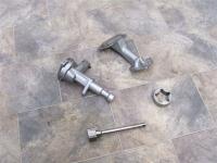
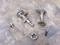
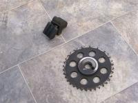
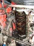
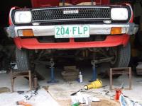
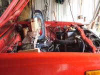
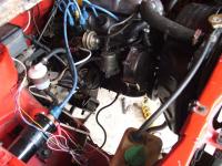
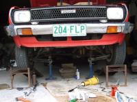
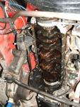
Well made some progess today, and found the problem, I hope ! Not wanting to pull the engine out again, I took the easy way out, by dropping the front cross member & getting full access to the sump. I had the sump off & oil pump in hand in just on an hour. The sight of the oil pump pickup screen, with small black fragments hanging all over it, gave me the horrors. Close examination showed they were not metal fragments, but bits of very hard rubber. When the timing chain had jumped on the sprocket, it bit badly into the tensioner rubber, & chewed it up like a chainsaw. The sump had lots of bits in the bottom. I carefully disassembled the oil pump & found the smallest fragments of a black substance, on the end of the pressure relief valve. The valve is a square cut device & is not self cleaning. I have seen tappered ones in other makes of cars that are to some extent self cleaning. I sorted through my 3K & 4K oils pumps & found a 3k one in remarkable condition. My yellow K series Toyota engine manual, which covers 2K to 5KC engines does not define any differences in specifications for any of the K series oil pumps. There are a couple of different configurations, including a picture of the one with a bolt on pickup that Tony referred to, earlier in this thread. (good book says bolt on pickup was fitted to KM20 series) I got out the vernier & steel ruler and measured everything I could & they all seem to be exactly the same. There seems to have been two main types, the ASCO & AISIN types. Anyway, I cleaned the sump, the 3K pump, checked all big ends & mains for damage, & replaced oil filter again. Just awaiting a new sump gasket which I didn't have, and I'll fire it back up on Monday, and hopefully confirm the problem was as described above. Thanks for the help guys ! :jamie:

-
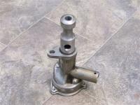
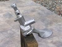
Jamie, here is a picture of the 5K oil pump, depicting the outlet at the top of the pump shaft. If you want my old discarded 5K pump for measuements or something, yell out, and I will post it down to you. :jamie:
-
Jamie, I'll take a picture of the oil pump outlet today, and post it this evening. :(
-
Thanks for those suggestions fellas ! Before the 5K went it, I had the head done up, and I pulled the sump off & cleaned the oil pickup, so I know that is perfectly clean. When the problem first appeared, it had a Ryco oil filter on it. Only a week ago I gave it an oil change & fitted a new Japanese Osaka oil filter, and the problem is the same, so I'm pretty sure it is not related to the oil filter. The distributor is a 5K electronic one, which I had rebushed professionally, before the 5K was fired up. It had a new pin fitted at the time, where the gear at the bottom of the shaft is attached to the shaft. The distributor is in excellent nick. I've measured all the lengths of distributor shaft and distance to oil pump locator, with distributor removed to make sure that the dog at the bottom of the dizzy shaft locates OK in the slot at the top of the oil pump shaft. The dog goes into the slot 5mm by my measurements, and that correlates with the pressure marks on the dog at the bottom of the dizzy shaft. The 5K still has the hydraulic lifters, and it is the ticking noise that has me baffled. I'd be glad if it was the pressure relief valve, playing up, but the ticking noise is not related to that. The tick seems to be at camshaft speed. I'll let you know what I find tomorrow, but would love to hear from you Doug as to whether there are any differences in the 4K & 5K oil pumps. :(
-
Hi Guys & Gals, Been out of the loop for a while as my bastard boss sent me overseas (H.K.) for a spell. But that's another story, and I'll just say I'm going to take him to Oxley's Hotel on Coro Drive for Christmas; get him drunk, tell him what I think of him; then throw him overboard ! I hope he doesn't read this forum ! He drives a Saab ! Not that I've got anything against Saabs. But you get the picture. Anyway, I'm back and have a problem I hope your collective minds can assist with. Heaven's Nicks been at work hasn't he. There's a thing down the bottom of this page called "Guided Mode Off" (are they fitting auto pilot to old Corollas now ? And another called "Check Post Length" A new reader could think we're in to building fences. Anyway, I digress. I'll be brief. KE55 with 5K now onboard has been singing along for several months like a bird, according to my better half. When I got in it after an absence, It was just great. Anyway, one afternoon while driving normally, there was a great mechanical crunch in the engine, a big sudder & then off she went again OK. This happen another two times before I got it back home. It sounded horrible, even terminal. After that there was a mechanical ticking noise. My first guess was the timing chain, so off it came. It looked all right, until I washed all the sprockets. The single chain had been riding up on the sprocket indicating the sprocket was bent. The sprocket was not bent. The last person to assemble the engine (not me) had left a little bit of swaft between the back of the camshaft sprocket & the end of the camshaft. The camshaft sprocket was running slightly out. As the chain was a bit stretched, and the tensioner was close to the end of it's takeup, the chain rode up, which had resulted in the crunch & probably stretched the chain even more. I didn't notice whether the chain had jumped a sprocket, cause I didn't take notice when removing same. Anyway, on with a double row chain and sprockets, (thank you Rob !) and we are back to normal; well almost. There is a slight ticking noise every now and then. I drive it for a week, and except for the slight ticking noise occasionally, it runs like a new one. Then, it does a horrible thing. The oil light comes on, and I rapidly pull to the side of the road. Visual inspection shows nothing, and I restart the engine, and it provides oil pressure & drives like a good one. Back in the garage, take the distributor out & check oil pump dog slot or anything that could cause sudden loss of oil pressure. Nothing obvious. As all I have on the dash is the oil pressure idiot light, I connect up an electric oil pressure guage so I can observe oil pressure whilst driving. It runs pefectly for a week, with driving oil pressure between 60 -70 PSI, and idle around 20 PSI. The all of a sudden the oil pressure starts fluctuating whilst driving, and drops quite low sometimes, but the engine stays as quiet as if it has full oil pressure. I even suspect the guage now, but after taking it out & putting it on another motoor, it proves to be working perfectly. So I've got a problem. I've never had an oil pump fault before in any car. After pulling another 4K oil pump I have to pieces, I can't see anything that could fail that would create a fault which results in pump working perfectly at some times, & low pressure at others. The only part of the oil pump that I could see being a problem is the relief valve & maybe it's associated spring. But then it occurred to me that the oil pump might be alright, but there is somewhere in the lubrication systems where something that is partially broken is dumping oil back to the sump & lowering the pressure. Tomorrow, the pump is coming out, and hopefully the problem will be clear to see. However, if the pump shows no problems, what else could it be. I have a few other 3K & 4K oil pumps here, so I was just going to change the whole pump out, and see whether it has an effect or not. Does anyone know if 3k, 4K, & 5K oil pumps are all the same & interchangeable ? Has anyone ever had a oil problem with any similar symptoms to those I describe. Whatever has happened to the pump, or something else mechanical. appears to clearly have happened when the chain jumped the sprocket. I'm here scratching my head, so any thoughts or suggestions your collective heads can offer will be gratefully accepted. :( :) :)
-
Awesome Tony ! Congrats ! * thinks* Quick I want to stand my 5K upright. :)
-
That was awesome ! Followed it for the last hour & a half on-line directly from NASA. What a blast ! So glad it all went well. :jamie: :dance: :dance:
-
Came across this picture of policeman circling car. Think he must be checking the suspension. (or bumper bars) =) :wub: :wub: :y:
-
Man is that fast, once around the earth every 90 minutes ! Hope there is some real-time coverage on tele tonight ! :y:
-
Here ! Here ! Finger Crossed ! :y:
-
Hey Mike, I'm not sure our "boys in blue" would fall for that one out here in Australia. They would defect you anyway, as we now have very strict regs. on diesel powered road vehicles. Love your cheek though ! Diesel here is now dearer than ULP. It used to be the other way around in an attempt to lure people to get into diesel powered cars. It all backfired, so to speak, and now they are trying to discourage it. Love your stories from the great USA. :y:
-
Another possibilty is the timing chain tick/click. All Toyota K series engines have a timing chain between crankshaft & camshaft that is prone to stretch. This stretch is taken up by a tensioner that is driven by oil pressure. When the oil pressure is very low, like at idle in an engine with a few klms on it, the tensioner does not work very well, & the slop in the chain can cause a tick or click. In the worse case, the chain can have so much "slop" in it that it can touch the timing case. I have never heard of a K series chain breaking, and there are stories that there have been timing covers that have worn through, with the chain slapping against it. Turn the idling back up again,and see if the tick/click goes away. The beauty of the K series is that they can have all the ticks & clicks in the world and sound like a bucket of loose bolts, but they still don't stop or let you down. To prevent timing chain stretch, the rule is that you replace timing chain every time you do a major overhaul on a K series, preferable with a double row chain & sprockets from a 3K which are a straight fit to a 4KC, to my knowledge. A good idea is to replace the auto tensioner at the same time. If the click is not there when you first start the engine from a cold start, when the oil is thicker, but appears after the engine gets up to operating temperature, then it is a good chance it is the chain. If turning up the idling gives a similar result, then it is also likely to be the chain. Don't worry about it. Turn up the music, and enjoy the ride. :y:
-
. . . . msn ch#9 report tonite. Can you believe this. A billion dollar project, and a multi-million dollar space craft and it doesn't even have a decent tool kit on board. They spend all this money training astronauts, when any RollaClub member worth his salt could have fixed the bloody thing, with what we carry around in the corner of our boots every day. And we would probably fix it gratis just for the opportunity to "drift" in space. *wonders if Andy Thomas ever had a Corolla ?* ;)
-
* has wicked idea* You know how blokes buy the rear end of utes and weld on a draw bar, & then use it for a trailer. Well . . . . . Take this Neon rear end, add a draw bar, and you've got a great little waggon to put the mother-in-law in when you have to take her out. And . . . . don't fill in the front :y: And . . . . hope it rains ! ;)
-
Correction ! That was a Neon. Or to be more politically correct. That's half a Neon ! :P :bash: :y:
-
-
Hi Greg ! Welcome aboard RollaClub. We all just love new members with digital cameras who can post some pictures for all of us to drool over. Glad you like the forum. If you haven't already, spend a night or two reading the Frequently Asked Questions (FAQ) There's a wealth of info in there that I'm sure you'll find interesting, gathered over a long time. SEARCH is another great function. If you see something missing, don't be scared to ask or even contribute. We are all here to learn . . . and have a bit of fun. Cheers ! :P
-
Not quite Fook ! The other way around. The crank spins at twice the speed of the cam & dizzy. Well, it did last time I looked. Therein lies the problem. All electronic crank sensing systems need a second sensing signal from a cam shaft sensor, or dizzy sensor like the Nissans, to tell the ECU whether the crank trigger is suppose to trigger cylinder no: 1 or cylinder no: 4 (in a 4 cylinder engine) TDC no:1 cylinder is the exact same rotational position as TDC no:4 cylinder, except one cylinder is on the end of it's compression stroke & the other is on the end of it's exhaust stroke. The same conditions occur with cylinders nos 2 & 3, except they are another 1/2 turn on, of the crankshaft, usually requiring another sensor. You are right about the flywheel providing greater accuracy, due to it's larger diameter. Without lathes and accurate machining facilities, trying to do this on the crankshaft pulley, leaves a lot to be desired. I know a lot of aftermarket systems use brackets that bolt onto the lower front of the engine, but I want my bits & pieces hidden safely away at the back of the engine. Stay tuned & all will be revealed. But please keep those comments coming ! :P
-
Teddy is closest to the money ! As the Blackadder said . . . . . "I have a plan so cunning, you could pin a tail on it." :P
-
My 6 year old is constantly asking when we are going to put the wheels & seat on the "engine stand thingy" ! I think he has visions of screaming around the backyard in/on it ! * evil thoughts enter another RollaCluber's mind ! * :P


