

Banjo
Regular Member
-
Joined
-
Last visited
Everything posted by Banjo
-
My pleasure ! You'll luv your KE25 with the 5K in it. It is by far the cheapest & simplest way to breath new life back into an older early model Corollas that are a daily drive. 5Ks are getting harder to find, but I believe Toyota still used the 5K in their petrol industrial forklifts up to the early 2000s, and you can still get exchange reconditioned 5Ks from the engine reconditioning exchange companies like Repco & GEM etc. When I first went looking for 5Ks years ago, I' thought I never find one. Now I've got two. They go best when mated with a 5 speed gearbox from the KE70. I've got a 4 speed behind one of mine, & a 5 speed behind the other, & there's no comparison when cruising. There are two mods you should always do when when transplanting a 5K. 1. Upgrade the front brakes. 2. Replace the single timing chain with a duplex (2 row) one from a 3K enginge. The camshaft & crankshaft sprockets swap straight over. Always replace the timing chain tensioner at the same time. You can usually find new ones on ebay. Also make sure that your 5K acquisition has an electronic distributor with internal ignitor module, & that no one has swapped it over for a points one during its previous life. Cheers Banjo
-
I confirm Stuart's advice that 5K flywheel & clutch won't fit inside the K40/50 bell housing. It's a tight fit in there. It's normal to fit the 3K or 4K flywheel to the 5K in these circumstances. Even with the 3K or 4K flywheel, you have to be careful. Not all after market pressure plates are the same depth. I once did a 5K conversion, fitted the 4K flywheel and after running the engine, heard this ticking noise. Traced it to the bell housing. Removed gearbox again, and found the outer top edge of the pressure plate was just touching the bell housing. Removed the pressure plate and lined it up on a flat surface with two others I had, and found it was slightly higher. I think the after market originated from India. I put one of the other lower depth pressure plate on, ground the bell housing slightly for good measure, & the problem disappeared forever. Cheers Banjo
-
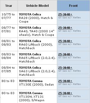
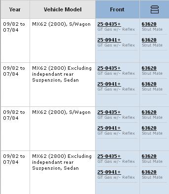
The struts had the original oil filled Toyota shock absorbers in them, when I got them, which had no part numbers on them. The Monroe GT Gas cartridges I bought were model 25-3648. When I search the Monroe website for 25-3648, it pulls up all the following Toyotas that this model suits. The MX62 Cressida does not get a mention, so maybe they are Celica struts, as I was advised, & there has been a bit of mix & match with rotors & LCAs by someone previously. The 25-3648 shocks certainly fit perfectly in the struts I have. Monroes lists the 25-0435 being suitable for the MX62 Cressida. Cheers Banjo
-
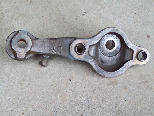
Hoping someone on here with access to Toyota part numbers can help me with this one. I bought a pair of struts from a guy here in S.E. Qld, but never saw the car they came from. Attached to the struts were the LCAs, the coil springs and perches, steering knuckles, & the top bearing block. There were no calipers fitted. I was told the whole assembly was from an RA65 Celica. I stripped them down & started to refurbish them. The struts are 51mm OD, and have the big hubs with PCD of 4 x 114.3. The rotors are bolted onto the hubs from the inner side of the rotor. The LCAs were the standard 300mm long ones that fit so many Toyotas. I bought a pair of Monroe gas shocks designated to suit RA60/65 Celica, and they fitted perfectly. I measured the KPI angle and it appeared to be about 9.0 deg. The caliper mounting points have exactly 100mm centres. I decided I'd order a pair of new DBA rotors, as once I skimmed, the ones I had would be on minimum thickness. With the rotors off the hub, I measured the rotors precisely, and was surprised to find the OD was 248mm, not the 258mm I expected, after researching the RA65 rotor sizes. So now I'm not sure whether the struts are RA65s, and someone has fitted the slightly smaller rotors at some time, or whether the whole assembly I purchased, is maybe off a Cressida MX62, which has 248mm rotors. However, my research indicates the Cressida MX62 had a much longer LCA. I searched the strut on the weekend, & the only number I could come up with on the strut tube, just below the Toyota symbol was WK-23S. Strange short number for Toyota, so I don't know whether it is the tube number, or the whole strut number, but it's the only number I can find on the strut. Any help would be greatly appreciated. P.S. The only other clue was that that the steering knuckles fitted, have the offset ball joint mounting hole. Cheers Banjo.
-
Have a read of a discussion about this on this site at http://www.rollaclub...owering-blocks/ I'm luv'in your car. The wheels look good ! P.S. Search our forums for "KE20 Lowering Blocks" and you'll find there are 4 pages of threads on this subject. Cheers Banjo
-
Hi, Welcome aboard ! A lovely little KE20 you've scored yourself there ! Looks like it is in remarkable condition, and a good starting point for a refurb. Has it got much rust in it ? I would love to have started with one of these, but many Ke20/25s in Australia are riddled with "the cancer", and the cost & effort to bring the body back to roadworthy, is prohibitive, unless you are a panel beater by trade, (which I'm not). I've got a granny KE30, which I acquired with 96,000 klms only, and a like new body. My dream would be to own an SR5, something like this one in the USA ! Sorry, I can't answer any of your queries, but there are are others on here that will, no doubt, have the info you need. Keep us up to to date with you progress with your "acquistion", and we wish you the best with it. Cheers Banjo


-
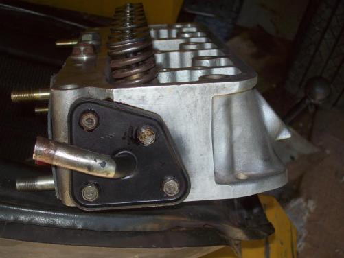
Hi Jader, The weekend before last, I blew a head gasket in my 4KU (no: 4 cylinder), which is in a KE30, which originally had a 3K in it. I took the head off, skimmed it, and refitted, but took the opportunity to take a photo of the head "rear cover plate", whilst it was out. It shows the plate, as fitted to some early 3Ks, where a heater pipe was attached/fitted, as described earlier in this thread. Be warned that the plates on the rear of 3K, 4K, & 5K heads are not all identical. I think one of the bolt holes on a 5K plate is in a slightly different position. Cheers Banjo
-
Hi Guys, Quick question. Does anyone one know off hand what the Cressida MX62 standard front brake caliper mount holes, centre to centre dimension is ? I believe it is 100mm, but not sure. I've Googled for a hour this morning, & can't find this info anywhere. I know there are some other Toyotas, that use calipers with 90mm mounting centres, but would like to find something that bolts up without the need to engineer a special mounting bracket. Cheers Banjo
-
Hi Brendon, Common fault with the olde KEs. The usual cause is the tiny 8-9V voltage regulator on the rear of the dash printed circuit board behind the guages, or the "sender unit" in the tank itself. Very rarely is the cause the guage itself. I assume you have checked all the fuses first. I'll see if I can't dig out the circuit for you. Cheers Banjo
-
Hi Will, Found this picture of conrod/cap matching marks you can do with a centre punch or drill. This is not a Toyota engine, but it gives you the idea. This is what Altezzaclub was referring to in his first post above. It tells you which rod & cap are a pair, & which cylinder it belongs to. Cheers Banjo
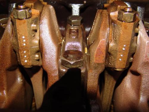
-
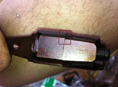
Seeing it was the girls that got you into this mess, then you should get them back around to sort it out for you. The casting number on the bottom of the bottom conrod slipper bearing cap means nothing. It is the stamped numbers on the side of the conrod & cap that should match. It could be that these are not original to this engine, and that they have been mixed up, or line bored as conrod/cap pairs previously. The rod & cap are usually ground in pairs on the side, where the numbers are eventually stamped. If you look at the third picture in your original post, it looks like the grinds do not match up. This may be because of the casting itself, but maybe because they were never ground together originally, and are a mixed pair. Cheers Banjo
-
I wish I could relate to all your story. What was the attraction. Did they drive a Corolla, or did you have a Volvo parked in your driveway at the time ? Do the pistons have 1,2,3 & 4 stamped on the top face ? Cheers Banjo
-
Good Heaven ! What have I started ? I had just got rid of the distributor on my 4K, replacing it with two Commo coils & a waste spark ignition system (DIS) Now I have to think about using that dizzy drive off the camshaft to run a fuel pump for a possble EFI conversion ? Happy Days ! Cheers Banjo !
-
Hi Guys, Rumours abound that Toyota may reintroduce the K Series Corolla. This is approx. 45 years after it was first introduced to the world. However, it is a very, very different Corolla, to the one we have all learnt to love. Unfortunately, none of the parts are interchangeable, so those of you who have got a shed full of bits & pieces; don't get too excited that you are in for a bonanza ! The other radical departure from the Corolla that we know, is that it has three, yes, three wheels. Now I know some of us have experienced three wheel travel in our Corollas, but that was usually not intentional. However, this new model has a great new feature that will find favour with those of you into Drifting ! The newest possible offering from Toyota will lean into corners ! Full details and pictures can be seen at the following link. http://finance.ninem...iroad.slideshow :no2: :no2: :no2: :no2: :no2: :no2: Cheers Banjo
-
I've narrowed down the spark plug selection to NGK BPR5EIX (Iridium) or NGK BPR5EGP (Platinum). These precisious metal plugs resists the erosion created by using the waste spark system where the HT current passes through the "paired" cylinder plugs in different directions. However, I've had a chat to Brodie in S.A. yesterday, who went through this whole thing several years ago. His findings were that . . . . . . NGK was the only plug worth considering. Unless the fuel mixture is near perfect, the precious metal plugs foul easily, & are hard to clean back to 100%. Re reverted back to good olde cheap copper NGK plugs, and just changed them when needs be, as he doesn't put a lot of klms on his KE30. A bit of research indicated that back in the 1980s, when waste spark first started to raise it's head, it was common, to swap the two spark plugs around, on the "paired" cylinders, so that the erosion was even on both electrodes, over time. However Brodie came up with a great idea which provides the simplicity of the waste spark system, without the issue of the erosion of plugs. He used four individual CoP motor bike coils on his 3K. I assumed incorrectly that he fired them sequentially, but he tells me he used a waste spark system where he fired the coils in pairs, so it is a waste spark system. Beautiful work Brodie ! Read Brodie's thread here . . . http://www.rollaclub.com/board/topic/47900-brodies-ke30-2door-supercharged-intercooled-megasquirt-cop-ignition/page__p__605291#entry605291 The only disadvantage is that you need four (4) ignitor modules, one for each coil. However very minimal ignitors can be utilised, because each ignitor is only firing one smaller motor bike coil, which are designed for much higher RPM than we'll ever see in a 3, 4, or 5K engine. Because each spark plug has a seperate coil there are no issues with erosion I've been using the Bosch BIP373 Mosfets as ignitors for the coils. I couldn't get them here in Australia, so I bought some from DIY Autotune in the USA. They are great, being almost indestructible, with overtemp cutout & current limiting. The nice thing is they can be driven by the output of an ordinary CMOS chip. So although the erosion of plugs is no great issue as yet for me, I may finish up using four motor bike type coils. Wouldn't it be great if I could find four coils small enough that they could all fit inside the original distributor cap. Cheers Banjo

-
-
-
For those that like researching these subjects, there was a good thread over on Toymods a few years ago, regarding the advantages of sequential firing of spark plugs vs wasted spak setups. http://www.toymods.org.au/forums/tech-conversions/10670-wasted-sparks-vs-sequential-spark.html Cheers Banjo
-
You can use the "same" spark plugs in waste spark systems, but the degrading/errosion of the spark plug centre terminal is different in each plug, as HT current goes from outside to centre pin of one spark plug, & centre to outside on the spark plug in the "mated" cylinder. It's the outside electrode that errodes fastest, when the HT current is reversed. Originally, when all the plugs were the same, you would swap "mated" cylinders plugs around at service to extend their life. Now there are special spark plugs pairs with one made with the outer electrode made of identical material to the centre pin. This is as good a description as you'll find regarding waste spark systems. http://en.wikipedia...._component_life Read the section on Effect on Component Life Cheers Banjo
-
The test stand is a no brainer. If you've ever done major work on an engine, fitted it back into the car, tried to start it & found you've stuffed up big-time somewhere internally, & have has to pull it all out again, to rectify; you'll appreciate the confidence that the engine runs well, before it's fitted to the car. I built the stand on a Saturday afternoon a few years back. Three or four 200mm x 50mm hardwood planks I got from the local nursery supplier. $ 20 worth of coach screws & bolts & nuts from Bunnings. Thats about it. All the other Corolla bits I had lying around. KE70 front cross member & radiator. The accelerator is a height adjuster off an old Rover lawn mower I scrouged from the tip. It allows you to set the revs at a constant setting with both hands free to tune. A quick coat of black fence paint & it does the job. Has some heavy duty castors on the side rails, so you can "park" it easily in the garage. Four blocks fit under the corners, when in use to prevent it moving around. Cheers Banjo


-
The idea had crossed my mind seriously. It should be possible to create a load equal to the 4K with a restricted agricultural type water pump & a couple of 44 gal drums as a resevoir. It would be nice to be able to fine tune the engine out of the car in a totally controlled enviroment. Only other thing I would need would be one of those large industrial fans in front of the radiator to produce the forced air you get through the radiator whilst driving. Cheers Banjo
-
There are a number of guys in Rollaclub that have waste spark ignition setups. One of the best executed ones I have come across is Brodies little project in S.A. a few years back. He's a perfectionist, and his mods are just beautiful. http://www.rollaclub...__ waste spark The waste spark system does simplify the ignition system considerably, with the best result being the removal of the need for the distributor cap, rotor button etc. You still have the option of using the distributor points or reluctor, to trigger an ignition module to fire the coils, but it does provide you the chance to get rid of the distributor altogether, if the ignition module has programable advance curve & MAP load retard facilities. The best opportunity offered is to trigger the ignition from the flywheel, rather than the camshaft driven distributor. This has massive advantages on older cars like most of our K series engines. The "slop" that is created in the drive between crankshaft & points in often underestimated. That "slop" in timing chain and distributor drive gear, results in an inconsistent firing point, and if you've ever used a timing light on the timing marks on the front timing chain cover & pulley, you've probably seen it jumping around up & down a few degrees. When you switch to crankshaft triggering, that mechanical induced instability into the triggering point is eliminated altogether. If you read Brodies build, you'll see he used a toothed trigger wheel fitted to the front of the crankshaft pulley. That is probably the most popular way of triggering. Most ignition modules accept toothed wheel sensors with a missing tooth indicating TDC no: 1 cyclinder as a reference point for the whole system. When I trigger off the crankshaft, the timing light indicates a rock steady timing mark at the crankshaft pulley. All other things aside, it changes the smoothness of the engine instantly, and the ability to be able to program advance curves lets you get the most out of the engine. Remember these engines were designed with performance to limit warranty claims & increase reliability. The number of KE series Corollas on the road still, is a testiment to that. The igniton system was one of the major ways of controlling/downgrading the performance of the engine. I am experimenting with another way of cranshaft triggering which is very simple. I trigger off the flywheel, using rare earth magnets embedded into small holes drilled vertically into the narrow rim of the flywheel between the ring gear & the clutch face. A Hall Effect sensor picks up the signals beautifully. I've even tried a linear Hall Effect sensor that can sense the difference between a South pole & a North pole, so that a common sensor can pick up all 1-4, & 2-3 triggering points. The system works well with a waste spark system, but is just as easily utilised with sequential firing each spark plug one at a time, which allows smaller coil on plug arrangement. If anyone is interested, I'll put up a few photos, as I have the 4K engine I'm experimenting with on an engine jig I built a few years ago. I take all my measurements at the flywheel, where I have a nice big degree wheel fitted. It's a great way to learn, and after I've perfected the ignition setup, I'll move onto incorporating an EFI setup, so I can incorporate all mods on the 5K I have awaiting. Cheers Banjo


-
-
Hi Charles, A multimeter is a good start to sorting electrical problems but an even better tool is a 12 volt 21W tail light bulb, with two pieces of wire soldered to it. Connect one side to the negative of the battery and the other end probe around. Place it first on the +ve terminal of the battery & then take mental note of the brightness of the bulb. Then place the probe on the common end of the fusible link & then on the three other individual ends of the fusible links. Good chance one of these has blown. You can also use your lamp tester to check earths. Connect one end of the test lamp leads to the +ve terminal, and probe around with the other end on common earth points like the chassis, the engine block, etc. Ensure the brightness of the lamp does not dim. This will indicate a connection, but also resistance in the circuit. The reason this is better than a multimeter, is that as well as checking continuity, it also detects resistance in wiring, fusible links, fuses etc. A multimeter is a high impedance load and shows continuity, even if there is resistance that may cause loads like lighting circuits to drop voltage due to corrosion, bad joints & the like. Hope that helps. If you work from the battery out on each circuit, systematically, using the wiring diagram, you should pick up your problem fairly quickly. Good luck ! Let us know how you go. Cheers Banjo
-
PM to me your address & I'll post the Gregory's manual today. Glad we could be of assistance. Cheers Banjo.


