

Banjo
Regular Member
-
Joined
-
Last visited
Everything posted by Banjo
-
It's a bummer when those bolts freeze & break. I've done it before, hence my warning. OK, centre pop the broken bolt very carefully, as close to the centre as you can get. Drill the bolt right down through the centre, through into the water jacket if necessary, with a sharp 3 mm drill. Keep the drill straight. Then enlarge the hole with slightly bigger drills until you almost reach the bottom of the threads of the bolt. Squirt it with WD40 & then try to get ease it out with an "easy out". If that doesn't work, then drill it our to the bottom of the bolt threads & then somtimes you can get it out with a tap. If all else fails, then there is usually enough metal in the head to go up a bolt size. One of the reasons these bolts freeze, is that the threaded holes are not always blind, and sometimes go right through into the water jacket, allowing the water to corode the bolt tip & head together. Good luck. Cheers Banjo. P.S. If you're down Greenbank way sometime soon, I've got a Gregory's manual in G.C. you can have for $ 10.00.
-
Hi Charles, Sorry, I read your line " getting a proper circuit" as getting a proper connection. Anyway you know about the bridge on the auto console. Here is a wiring diagram for the KE30/KE35. The Corolla's wiring diagrams are pretty much all the same basically, although there are some subtle differences. I have a KE30, and here is a wiring diagram I have used for a couple of years, & found all the wire colours and connections are pretty true to what it actually is. Just for the record for any others following this thread, here is a wiring diagram showing the park / neutral switch. Right click on these above wiring diagrams one at a time & save them as a .jpg files. Print them out, and then join them together, and it will make it easier while working on the car. P.S. I printed 2 originally, and always keep one in the glove box. Trust this assists. Cheers Banjo


-
Hi Charles, Would the KE-30 have had a automatic transmission fitted to it before you just fitted the K40 4 speed gearbox ? If so there is a bridge required for the wires that went to the shift console. I'm sure I've seen it documented elsewhere on this website. Basically I think it is bridging out the wires that prevents an automatic being started unless it is in park. Anyway, let us know whether you previously had an auto, and we can then help you get it going. Cheers Banjo
-
-
Jeff & Rone are right. The plate is there for moulding of the aluminium head, so they can remove the "sand" or whatever they used to fill the water jacket areas during head manufacture. On most K motors, the plate is just a blanking plate. On some K series, one of the heater water lines is connected to this plate, as Rone states. Most K series users have had this problem at some time. Unfortunately, it's in a horrible position, & requires the head to come off. Be very careful taking the plate off, as it is very easy to strip the threads in the head, if bolts are frozen. You will often find when you remove the plate that you are met with a lump of "muck" up against the back of the plate. This often eats/corrodes through the plate, so the leak could well be through the centre of the plate, & not the gasket at all. If this is the case, you will have to replace the plate itself. This build up is because the water flows are not very good around the back of the head, as coolant flows in & out of the engine to the radiator through the front of the engine. Invariably the no: 4 cylinder runs hotter than all the rest, and it is not uncommon for no: 4 cylinder to be the first one to have a ring/wear or pistion problem. I've even heard of some racers using a lower heat range spark plug in no: 4 cylinder, because of this. A mod that is often carried out on race cars, is to feed the water from the rear of the head back to the radiator to assist in better water flow through the rear of the engine. Cheers Banjo
-
Well, I determined that the exact preload in the front coil springs is really a secondary issue, and that the real issue is ensuring that there is clearance between the lower spring perch on the strut, & the tyre & wheel you are using. I went and assembled an original KE70 strut & spring, and measured the free length & compressed length of the standard spring. The difference, or preload, in these two dimensions was exactly 90mm. I then temporarily fitted the lower KE70 perch in a position on the RA65 strut, so that it cleared the tyre OK. I then fitted the KE70 spring compressed, and low & behold, the preload compression was exactly 90 mm. This shouldn't have been any surprise, as the KE70 & Celica RA65 strut are exactly the same length. So just awaiting King Springs to deliver two new KE70 standard springs in the X5K coil sping material to finish it off. I'll post some pictures as soon as they are all together. Cheers Banjo
-
OK, I'm back from holidays, and back into this brake upgrade on my KE30, after the big wet here in Brisbane. Today I have the Celicia RA65 strut hanging upside down in my garage. It is fully assembled with KE70 standard springs, new RA65 gas shocks, KE70 top spring caps, and bottom KE70 spring perches, which I have carefully ground out, to fit the RA65 51mm dia. strut. I have not as yet welded the bottom spring perches to the strut itself. All I need now, is to determine how much preload or precommpession to put on the spring, to kept the spring captive, when a front wheel becomes air borne, and the wheel droop is at it's limit. It appears to me that somewhere around 10 - 20 mm would be about right. With a coil over, you just wind it up until you get it right. When you fit spring perches, you only get one go at it. Is there any rules of thumb for how much preload you need to put on the spring to keep it capitive ? I'm a bit confused, as the article at the following link on adjusting coilovers states you should have zero preload on the coil spring. http://www.meganraci...spring pre-load Would be interested to hear from others with experience in this area. Cheers Banjo
-
Hi Reed, That's exactly where I am looking. I believe that Industrial Bearing Suppliers are Ruland agents in Australia. I'm planning on giving them a ring tomorrow, and see whether they have the split models I have picked out as being suitable. The Ruland range is massive, so I can't assume they would not stock the lot. Cheers Banjo
-
Hi Guys, I accurately measured the section of the clutch cable where the C Clip is fitted. It has an outside dia. of 13.8 mm. The grooves are exactly 1.00 mm deep & 1.00 mm wide. A new C clip is exactly 1.00 mm thick. That would make the dia. of the bottom of the grooves for the C clip 11.8 mm. I'll now try and find a "clamping collar" like Hadyn's above that has the appropriate dimensions. Stay tuned !
-
Hi Haydn, That's perfect. Thanks for the tip. They are called locking or clamping collars, and are usually sold by bearing suppliers, or engineering or fastner suppliers. I Googled images of clamping collars, and there are lots of different varieties. Tomorrow I'll measure up the clutch cable with a vernier, & get some dimensions & a part number of a suitable one. A great idea would be to get one with an inside diameter, the same size as the clutch cable sheath dia. at the bottom of the goove, where the "C" clip sits. You could then machine the collar out slightly from either side, until it left a little section in the middle, that could sit down in the groove, and really locate it perfectly. Cheers Banjo

-
Can you still puchase those clutch adjuster circlips from Toyota ? I haven't tried, as I've always had a donor car close by or removed one when at the wreckers. A couple of new ones would be good as they would have clean edges, and I like the idea of using two with a spacer in between to give the extra hold required. Cheers Banjo

-
Oh dear ! No spigot bearing ! A very easy trap. I once accidentally fitted a new clutch plate which was 21 spline instead of 19, although the cardboard box was labelled 19 splines. What a horrible noise when the clutch was let out for the first time. Again, like you, it was back out with the gearbox again. I hate doing things twice ! Well now we all know ! Let is know how you go once you've fitted the new spigot bearing. They are so cheap at a "bearing shop" I make a rule of always changing mine, any time I have a gearbox or clutch out. Cheers Banjo
-
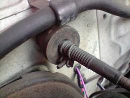
I've been tempted for a while to do a hydraulic clutch conversion on my KE30. However, my wife never complains of a heavy clutch pedal, and the cable arrangement is simple & generally reliable. I've found the only problem you have with the cable is it going "dry" on the big radius. Every couple of years I pull the cable out & hang the outer sheath vertically in the vice. I then move the inner cable up & down, & squirt some light engine oil down into the sheath, until it drips out the bottom. That way I know the whole cable is oiled. I once bought an Asian aftermarket cable for a KE, and it was terrible. It didn't have the Teflon lining over the inner cable like the Toyota OEM cable, and it bound on the large radius. Even generous lubrication did not help much. The design of making the clutch adjustment accessible in the enging bay was a great Toyota idea. Most cars require you get under neath ot put it on a hoist to adjust a threaded rod with lock nuts. However, the firewall adjustment of the KE series leaves a lot to be desired, as the little clip breaks, pops out, often never to be seen again. I guess most Rollas of that vintage have something like the following to replace the little C clip. The wire hose clamp seems a better idea that the band type as they resist slipping. I've found that I need two small band ones in series to take the forces involved. I've often thought of making a threaded tube, which could be attached to the outer sheath, with a couple of large adjusting lock nuts. I've not come across any aftermarket device or design on the net. I would be interested in hearing what others have improvised on RollaClub, or whether anyone has a good design alternative. Cheers Banjo


-
Hi Logan, My guess is it is related to fuel, and not to gearbocx mechanical, or an ignition problem. Did you do the conversion with the engine still in place ? If so you would have had to tilt the engine back down. There is an electrical wire on the carby of the far side. This wire is always powered when the ignition is on, and opens a solenoid in the carby to allow fuel to flow. It's purpose is to cut off fuel as soon as the ignition is switched off, so the engine cannot run on. However if there is an intermittent connection between carby and inner guard panel "green" connector, you can get a symptom, similar to what you are describing. This wire, being connected to the engine, vibrates, & if there is a bad connection, could easily be intermittent. I trust it is just that, because it's a very easy fix. Cheers Banjo
-
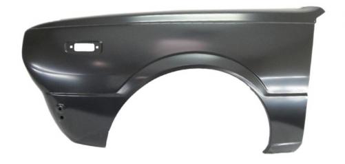
Hi John, Most definitely all KE30/35/55 front guards are completely interchangeable. The only difference you will ever find in these guards is that if they are imported spares from S.E. Asia or Japan, they may have holes in the top of the guards for mounting of "fender rear vision mirrors". Easily covered from the inside & filled. Also be wary of reproduction model panels which do not always fit well. There was a recent post on here under KEXX Corolla Discussion forum regarding these at . . . . http://www.rollaclub.com/board/topic/64044-ke30-reproduction-body-panels/ Cheers Banjo
-
-
-
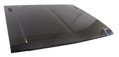
Hi Guys, Came across these at a ebay store called RRR Auto Parts in Sydney. Their store link is http://stores.ebay.c...sid=p4340.l2563 Has anyone purchased or used these ? I'd be interested in quality & fit. Any feedback appreciated. I note that this store also stocks some KE70 & AE71 panels also. Cheers Banjo
-
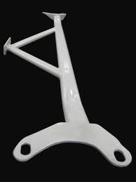
Finally got around this weekend to modifying the other KE30 steering arm so they would fit to the bottom of the RA65 struts. I ran into a slight problem, once the KE30 steering arm was attached to the lower ball joint, & I then I tried to attach the RA65 struts. The mating surfaces of the upper side of the steering arm, and lower end face of the struts would not come completely together. (gap of about 1 mm) This was because the tip of the ball joint threaded taper was touching the inside bottom of the strut. This is not an issue with the RA65 steering arms, (shown below) as they are deeper, & have a recess in them to accommodate the ball joint and retaining "castle" nut. I did find that not all lower ball joints are made equal. I have a couple of brand new brand "555" Japanese replacement ball joints to put in finally, and their threaded section & "castle" nuts are not as high. To quickly test, I ground the protruding section of the ball joint thread back to the top of a shallower nut. These ground ball joints will not be used again, so it didn't matter. With everything now in place, it was time to drop the donor car onto the dead level contrete floor & measure the camber. The results were dissappointing. My original calculations earlier in this post said I should finish up with about negative 0.6 deg camber each side. What I finished up with was negative 1.3 camber on one side, and positive 0.1 deg on the other. Now it might not be the same when I put these in the final KE30, but it goes to show the problem of camber in these early mass produced Corollas with no suspension adjustment facilities whatsoever. The major problem is that the two critical mounting points for the front suspension, being the inner LCA pivot point, & the top hat of the MacPherson strut are on two different parts of the car. The LCAs are connected to the cross member, whereas the top of the struts are connected to the body. I have often wondered how much 'sideways" movement is available in the cross member to the chassis, and may undo the four cross member to chassis mounting bolts, and try this next time I have an engine out. To my way of thinking, you could probably jig the car on a straightener in a body shop & then seam weld the car in the front area, but there is no guarantee that it would all come out straight, and the cost would be great. The idea of a triangular strut brace between strut towers & to the mid point of the firewall is looking like another cheaper option option. Something like this. I'll put the struts in the final KE30 car & see what camber result I come up with. I may then have to go to camber adjusters to get both sides equal. Any one got any ideas on the best KE camber adjusters available locally ? How many degrees of camber adjustment can you get out of these ? Cheers Banjo


-
For any newbies or others that haven't really got a hold of the jargon around suspension matters, the following website might be of interest. http://www.barsomtir...index.html#head I haven't come across another website that puts all the terminology in such simple concise terms, with good clear diagrams, all referring to Macpherson strut arrangements, which we Corolla guys all know well. Cheers Banjo
-
Hi Bruce, I spend a whole Saturday several weeks ago, with my KE30 on the garage concrete floor, with everything level. I even matched all wheel/tyre pad areas with offcuts of lino, so that each wheel contact area level was exactly the same. A good idea I picked up from the internet, is to use two pieces of lino face to face under each front wheel. You can smear the mating faces of the two lino pieces with grease, and this lets the wheels settle properly after bouncing the front of the car up & down. If you don't like the idea of the grease, then coarse salt spread over the lino does the same thing. It also lets you turn the steering wheel, with the car stationary, with little tyre drag. Anyway, once I had the whole car balanced & level, I measured the camber on both sides accurately, with the digital inclinometer. One side was perfectly vertical at zero camber, whilst the other side was 0.7 deg of positive camber. What I’d like to finish up with is about 0.5 – 1.0 deg of negative camber on each side, but exactly the same. The link on Reocities is one I’ve had book marked for quite a while. It’s full of good advice, & I guess gets scanned regularly. It’s a bit of a bible on old Corollas. The steering arm modification to allow the KE30/55 arm to attach to the bottom of the RA65 strut is pretty easy. You could buy one of those after market machined ones from the good old USA for $100 - $200 a pair, or pay an engineering firm to fill & redrill the holes. I think I've even seen the machined ones on ebay, but probably not for KE Corollas. I found it quite simple to elongate one hole (arm end) with a “ Bunnings ” carbide cutter costing $ 30.00. Here’s what it looked like when I’d finished it. I don’t think I will have any bump steer problems, as I have not changed the geometry of the front suspension & steering in any way. The RA65 struts are the same length as the original KE30 ones, and the LCAs are exactly the same length. I’m using the original steering arms & the tie rods are unchanged. From the way I read it, if the tie rod length is very close to that of the LCA, and the inner tie rod pivot point is in line with the LCA inner pivot point, then the arc of the tie rod & LCA should be very similar, with minimal bump steer. The problems with bump steer really starts to rear it’s ugly head, when cars get lowered with cut or lowered springs/shortened struts etc. That’s when you have to start adding RCAs to correct for it. As this KE30 is being prepared for a round Australia trip, not drifting or racing, I don’t think it will be an issue. However, once I’ve got the camber & castor sorted out, I will be checking the bump steer which isn’t too hard. A plate bolted across the hub faces, a dial gauge, & a jack under the strut. There’s a couple of good videos on the net, which depict the technique for DIYers well. Cheers Banjo


-
Hi Guys, Had an interesting weekend, experimenting with different settings on my donor KE55, using the Celica RA65 strut, with the bigger hubs & bearings, and the larger vented disks. I started by doing KPI (kin pin inclination) angles for the KE30/55, KE70 & RA65 struts, all of which I had here. For these I used my newly acquired digital inclinometer, which has a resolution of 0.1 degrees, so it’s accuracy is probably +/- .1 degrees. KE30 & RA65 struts & disks side by side. (RA65 strut has had lower perch removed) I took readings on the strut & hub face; taking two readings on the hub face, 180 degrees apart, to make sure of consistence readings. From the Toymods website I found the following table of KPIs, that members had provided. However, it did not include KE30/55 or RA65 KPIs specifically. RA40 8.4 deg. KE70 8.4 deg. RA28 8.4 deg. TA22 8.4 deg. XT130 8.4 deg. MA61 10.6 deg. MX83 13.1 deg. For the KE30/55 & KE70 struts, I came up with readings of 9.0 & 9.1 deg respectively. The RA65 came in with a reading of 8.4 degrees, which lines up perfectly with that for the RA40 in the table above. So it looks like the Corona XT130/XT132, & Celica RA40/RA60 & RA65 all have the same KPI of 8.4 degrees. Bear in mind that everything else being equal, a bigger KPI angle, should lessen the amount of negative camber, or increase the amount of positive camber, depending on whether the camber was originally negative or positive, however there are a number of other factors that come into play, as I discovered. As I haven’t got my final KE70 or AE86 springs as yet, I temporarily set up an RA65 strut with the original KE30/55 spring & top spring cap & hat. The RA65 strut being the same length as the KE30/55, & both LCAs also being exactly the same, the strut fitted in perfectly. I used the original RA65 steering arms, as the mounting centres on the KE30/55 ones are 2-3 mm shorter in the distance between the strut mounting holes. I dropped the wheel to the ground and settled it, and measured the camber with a straight edge cut to length, across the wheel rim vertically. I was pleasantly surprised that the result was a positive camber of only 0.3 degrees. I was concerned from warnings on this & other websites, that the use of RA65 struts would create severe positive camber. Clearly showing ball joint centre outside centre line of strut with RA65 steering arm However, the steering arm for the RA65 has it’s lower ball joint mounting hole offset inwards from the centre line of the strut. I figured that if I reversed the steering arm, the offset would work the other way, placing the bottom of the strut further outwards, providing some negative camber. It only took 10 minutes to reverse the steering arm & drop the wheel & remeasure the camber across the wheel rim. I was pleasantly surprised to find that the camber was now a healthy – 1.5 degrees. Large gap now produced between back of disk & outter tip of LCA The affect of reversing the steering arm provides a 25mm outwards change in the position of the lower strut mounting point to the cetre line of the lower ball joint. RA65 strut with KE30/55 spring inside the KE30/55 tower Sounds great, but obviously you can’t have the steering arm pointing towards the front of the car, and you can’t reverse left & right hand steering arms, as the arms have a bend in them. As I was looking for somewhere between 0.5 to 1.0 degree of negative camber, I figured that if I could use the KE30 steering arm, then it would provide only half the movement achieved with the RA65 steering arms, as it’s ball joint mounting point is in line with the strut mounting holes. In theory, the change in lower outward position of the strut should only be 12.5 mm, instead of 25mm. If the 25 mm had provided a change in degrees of 1.8 degrees, then 12.5 mm should provide 0.9 degrees. That would theoretically provide a negative camber of -.0.6 degrees, which is a good starting point to adjust from, if camber top adjusters are eventually needed to fine tune it & get each side of the equal. However, the problem is the KE30/55 steering arms won’t fit the RA65 struts. I did find a post on here where Radrollaz back in 2007, had an engineer remachine the KE30/55 steering arm mounting holes & locator rings to line up with the RA40/RA60/RA65 mounting holes. Radrollaz's engineered steering arm Being impatient, I took a carbine drill cutting tool & my high speed drill, & 25 minutes later the mounting hole in the KE30/55 steering arm at the arm end had been elongated, & the locator ring reinserted. We then copped another storm, so I couldn’t fit & prove my theory, of achieving the 0.6 degrees of negative camber, without changing steering arms, but will do so later this afternoon, & post the results. If it works I’ll take the car down to a specialized wheel aligner, with all the good gear, and have all my measurements confirmed. More to come . . Cheers Banjo


-
Hi Bruce, To my mind, there are a number of things that affect the camber, beyond the simple kin pin inclination (KPI) of the particular strut that is used. The vertical & horizontal distances between the centre of the strut top hat mounting, & the inner pivot point for the LCAs, are crucial to the gemometry of the camber. Secondly, the distance between the inner LCA pivot point & the lower ball joint mount centre also has an effect. Getting an alternative strut the same length as the original strut certainly helps, as does using LCAs the same length. However, the LCA outer ball joint centre line is not always exactly in the centre of the strut tube. Various steering arms made by Toyota have the lower ball joint offset from the centre line of the strut, presumably to set the camber to what they wanted. The picture attached, borrowed from the Toymods site shows this clearly. In fact the RA65 steering arms, which I have, do have the lower ball joint tapered hole offset. It's for these reasons, that KPI is not something you can decide upon wholly. That's why I am setting it up in a donor KE55, so I can put the car wheels back down on the deck, and measure the camber accurately using the inclinometer across each front rim vertically. When I get it all right, I'll just transfer everything across to the KE30, without having her off the road, as I use it as a daily drive. Will keep you posted of results. Cheers Banjo

-
Hi Bruce, Two weeks ago, I got one of those little digital inclinometers from Hong Kong on ebay for $ 20.00, the same as in the Toymods post, and have taken a number of readings of the KE-30 camber across the rims on a dead flat surface. I've also set up an RA65 & KE30 strut in the vice at the same strut angle exactly and the stub axles look pretty much in line. I will now repeat the exercise with KE30, KE70, & RA65 struts, all of which I have here, and take the exact measurements with the hubs on, which should give very accurate KPI readings, which I will post on here for you. However, with lots of different length LCAs available, it shouldn't be too hard to get the camber right. I'm not looking for anything excessive, just maybe 0.5 to 1.0 deg of negative camber. Cheers Banjo
-
Hi Guys, I'm half way through doing a brake upgrade on my KE-30 two door coupe. (early Corolla's are not known for they amazing brakes) I researched all the other options people have posted on here over the years. I've managed to obtain a set of front RA-65 Celica struts, complete with brakes & LCAs. These appealed to me, as I get the bigger hubs & bearings on the front wheels, & the big vented disks. Mate it up with a Pajero 1" bore master cylinder, and my KE-30 should stop on the spot. The RA-65 LCAs & strut lengths, are the same as the KE-30s. The only major mod required is the replacement of the lower coil perch on the RA-65 struts, as the strut towers on the KE-30 are too narrow for the RA-65 springs, which have an OD of approx 160mm. Lots of posts say that there will be postive camber issue with this type of upgrade, but my measurements to date indicate that, if there is a problem, it will be small, & can probably be corrected with a camber adjustment plate or slightly longer LCAs. I've already got 14" mags on the KE-30, and the wheels fit easily over the RA-65 hubs & brakes, with plenty of clearance to the lower spring perch. I originally decided on KE-70 front coils, as they have a smaller OD (125mm) than the standard KE-30 ones at 145mm. This would give me maximum room for movement in the KE-30 tower space if camber adjustment is needed. I obtained some "donor" KE-70 struts & have removed the lower spring perches, and opened them up to fit the 51mm OD RA-65 strut tubes. I was without top spring caps for the KE-70 struts, but I got two which are actually AE86 top spring caps, which I was told would fit the KE-70 springs. However, the AE-86 spring top caps are slightly too small for the KE-70 spring. I assumed then that the AE-86 front coil spring must be even smaller in OD than the KE-70 one. A bit of research on Google has turned up that the AE-86 front springs are 120mm OD. As I haven't purchased new King springs as yet, I thought I might as well go for the AE-86 coils instead of the KE-70s, as I've already got the AE-86 top spring caps, and it will result in even more room in the strut tower. The only question is, will the bottom of the AE-86 front coil spring sit snuggly in the KE-70 lower perches ? If there is anyone out there who can confirm that an AE-86 front coil spring is 120mm OD, and can advise if it will fit the KE-70 lower perches, I would be most appreciative. P.S. I am documenting this upgrade with pictures as I go, so will post it all on here when completed. I have a donor KE-55 set up in my garage that I can experiment with, then swap it all over to the KE-30 when I get it right. P.S.S. The only other question is what multi pot calipers are around, that will replace the original RA-65 ones, without any mounting bracket changes? Cheers Banjo


