All Activity
- Today
-

ELECTRIC FUEL PUMP WITH SAFETY PRESSURE SWITCH
altezzaclub replied to knibusu's topic in KE70 Technical Questions
"You approach a big curve in the road, & the sideward force moves the oil in the sump, sideways; & the intake pickup for the oil pump, grabs some air, as it is now not totally covered with oil. An instantaneous switching of your oil pressure safety switch, turns the engine off." Actually, a hesitation, hardly noticeable but Josh picked it up in the Evo5 at the Night Tarmac Sprints in Sydney. Luckily Steve the tuner was there that night and stuck his laptop on the roof and went through the data. He expanded a few traces to milliseconds and found the oil pressure had a hiccup on some corners, and as the safety cutout was set to 48psi it cut the ignition for a cylinder or so. Its still a good idea for an accident, like the dual relay cutouts for fuel pumps in injected cars, you have to have the fuel pumps turn off when the engine stops, even with the ignition on. That was in the COR box I fitted with the 4AGE and factory loom, and now the Haltech incorporates that feature in itself. That wiring diagram looks good, it has everything you need. - Yesterday
-

ELECTRIC FUEL PUMP WITH SAFETY PRESSURE SWITCH
Banjo replied to knibusu's topic in KE70 Technical Questions
The more I think about this technique, the more questions it raises, in my mind. The motor racing industry, may well require such a device, but for a normal road car, the implications of low or lack of oil pressure, whilst driving, & the engine just shutting itself off, outside of your control; could be extremely dangerous. The oil safety light on the dash of most cars is really all that You require. Have a read of the comments at this link. https://classicbroncos.com/forums/threads/wiring-electic-fuel-pump.43215/ When you first turn the ignition key "On"; before trying to start the car, the dash oil pressure warning light comes on, which tells you, "that the oil press sensor is working". When you start the engine & the oil pressure is generated, the warning light goes out; & You definitely know that the oil pressure is present & working OK. I suggest, that if You are concerned, or interested about oil pressure, in your engine; that You fit an oil pressure guage, to your dash area. You will learn more about oil pressure watching that over time. I simply think, that providing your car & engine, the ability to shut down the engine, whilst You are driving; "outside your control", could be downright dangerous. eg: You are highway driving, at say 100 klm/hr. Your oil level in the engine, is a bit on the low side. You approach a big curve in the road, & the sideward force moves the oil in the sump, sideways; & the intake pickup for the oil pump, grabs some air, as it is now not totally covered with oil. An instantaneous switching of your oil pressure safety switch, turns the engine off. You are on a curve, at elevated speed. The possible ramifications could well prove fatal, if You lose control. I could not imagine a rally drivers, ever considering fitting such a protection device to their engine. That engine gives one cough, whilst drifting sideways with opposite lock, on a dirt road, among the trees, is a complete "no no" to my mind. I'm open to others point of view, but personally, I do not think, it is a useful addition, to your road car. P.S. When assembling a fully reconditioned engine, all the bearing areas, are "assembled wet", with oil. The engine may also be turned over by the starter motor, without spark plugs or ignition connected, so all oilways in the block & head are filled. The only other situation, I can imagine, which might require such an action; is if an engine has been sitting for years, & is being started for the first time. Remove the plugs & turn the engine over, on the starter motor, is a common precaution. On top of that the Facet electric fuel pump, is a fairly expensive & highly sophisticated fuel pump, which is self adjusting, & provides a constant pressure, according to the maufacturers description. Would like to hear others thoughts on this matter. P.S. As a matter of interest; where did you mount the Facet Electronic fuel pump ? Is it in the boot area, adjacent to the fuel tank, or up in the engine bay somewhere, close to the engine proper ? P.S.S. Is this a transducer for an oil pressure guage ? Cheers Banjo
-

ELECTRIC FUEL PUMP WITH SAFETY PRESSURE SWITCH
knibusu replied to knibusu's topic in KE70 Technical Questions
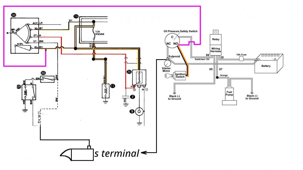
So after some further investigation I have found what I am looking for two ways to do it with or without relay and this diagram shows with a relay and what wires go to the relay. So basically the below diagram is the completed wiring and setup BO, will be the best 12 volt source for me and should work like I want it, I will probably set it up with a relay probably the safest option a bit more wiring involved but thats okay I will let you know how the setup goes.


-
ELECTRIC FUEL PUMP WITH SAFETY PRESSURE SWITCH
knibusu replied to knibusu's topic in KE70 Technical Questions
Sorry I should of stated the purpose, I am getting rid of the mechanical fuel pump and wanting to install the electric fuel pump, so my Idea on the oil pressure safety switch is, when the car is cranking gets 5 psi oil pressure the O.P.S.S will sense oil pressure and turn the fuel pump on, then when the car starts it will run off 12 volts on running. The only reason I am using the O.P.S.S in case my car dies such as stall the car while driving, lose oil pressure, crash worse case scenario, the fuel pump is not constantly on and pumping fuel. Yes I know you can do it with the relay setup and I was considering that https://www.hotrod.com/how-to/safe-and-efficient-electric-fuel-pump-wiring But the O.P.S.S is different PSI this switch operates at 7 PSI, three terminals S, I, P The holley switch operates at 5 PSI, three terminals N(normally closed), NO(normally open), C And the stock KE70 operates at 0.4 bar, so the holley is better in that way, I guess really all that means is the car will shut off quicker if it senses low oil pressure if you use the S,I, P switch. and with the three different terminals I think you have a different wiring setup. Also Banjo I think you are also correct, I forgot to mention this is also another way Holley says you can wire the Holley Oil Pressure Safety Switch. They just didnt give specifics on the relay so I opted for the easy route the one without the relay. Yeah the only reason why I am wanting to hook it up like this is just safety I could just get the fuel pump, and positive from pump to ignition on running source with inline fuse, and earth from fuel pump to body chassis and be done with it but that would mean as soon as I get 12V the pump is pumping so, like if my car is in on position but not running the pump would be pumping fuel still, the idea of the Oil Pressure Safety Switch is just safety and peace of mind for me, knowing that the fuel pump will be only on when the car is cranking and car running engine running.

-
ELECTRIC FUEL PUMP WITH SAFETY PRESSURE SWITCH
Banjo replied to knibusu's topic in KE70 Technical Questions
I really think there is something wrong with the circuit above, or the logic of operation. Did You obtain this circuit from this website link below ? https://www.jalopyjournal.com/forum/threads/oil-pressure-safety-switch-wiring-help.1112142/ Further down the page a relay is incorporated. I'll have a think about this. Is your purpose for fitting it, to not allow the engine to fire up, until the oil pressure during cranking, is enough to prevent a "dry cranking" situation. The needle valve in any carburetor usually stops any fuel from entering the carby, once the fuel bowl is full. The needle valve simply opens & lets more fuel in, once the fuel level in the carby bowel lowers slightly. This action keeps the fuel bowl constantly full, & to a certain level. Most engine regimes don't turn an electric fuel pump off. Are you trying to "stop the engine from starting", until the starter motor cranking, has built up some oil pressure ? As stated earlier, if You want to set this up as an accident scenario, where the fuel pump stops, on impact; then You need a G force sensor on impact switch, to turn the fuel pump off. I'll come back to You tomorrow, after I have a think about the logic behind this. I can see some need for an arrangement like this, in maybe a racing car; but not a road car. Cheers Banjo
-
ELECTRIC FUEL PUMP WITH SAFETY PRESSURE SWITCH
altezzaclub replied to knibusu's topic in KE70 Technical Questions
Yes, BO before it goes through the ballast resistor. -
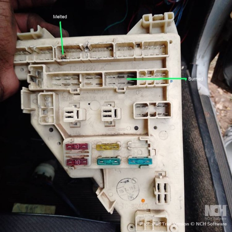
It looks like there has been some electrical damage to that relay box. Have you had the car running correctly in the past or has it always had problems?
-
ELECTRIC FUEL PUMP WITH SAFETY PRESSURE SWITCH
knibusu replied to knibusu's topic in KE70 Technical Questions
Yeah its carby, weber 32/36, its just one of those 12v 4 - 7psi fuel pumps I just want to know which ignition switch wire will have constant 12V when the car is on running, so I assume it would BO as that is also connected to dizzy I believe and this will supply my 12V to run the fuel pump when car is on running, and if ever the oil pressure safety switch sensors pressure below 5psi it will shut the fuel pump off.
-
ELECTRIC FUEL PUMP WITH SAFETY PRESSURE SWITCH
Banjo replied to knibusu's topic in KE70 Technical Questions
Nice diagrams ! I'm assuming that this engine has a carby, & is not fuel injected, which use much higher pressure fuel pumps. There are two types of electric low pressure fuel pumps for carby fuelled engines. There is the electric rotary motor type, which just runs all the time, & there is the diaphram type (like the old British SU fuel pumps), which only power up & pump, when the pressure on the outlet drops. The most common form of "emergency cut out" switch for electric fuel pumps is an impact type switch. These are usually rated at around 10G force activation, in case of an accident, or collision. Just because a car is in an accident; does not mean that the engine will stop turning. I've seen a crash, where the engine just sat there & screamed; & the only way was to remove a lead from the battery. The last thing You want in an accident, is to have a fuel pump, continuing to pump fuel onto a hot engine, & creating/causing a fire. I'd check the transport website in your area, as to what they stipulate. Cheers Banjo -
Not real sure what You are trying to advise ? When You turn the ignition key, to the start position, & the starter motor turns over; but when You release the key, the starter motor continues to turn ? I'd think it would more likely to be the starter motor itself. It might be that the throw-out solenoid, or something mechanical is worn, or at fault. Could also be an ignition switch mechanism gone ? First & easy test, as You think it might be electrical, is to remove the wire from the starter motor solenoid, & connect it to a 12V automotive bulb or test lamp to ground/earth/chassis. Test that it only lights, when the ignition switch is held against the return spring, in the "start" position. Not sure what You mean by, "I recently removed this wiring and I am not sure if it correctly done." The starter motor is permantenly connected to the +ve & -ve terminals of the battery. The starter solenoid, (within the starter motor) switches the +12V at the starter motor to the windings, inside the starter motor itself. Cheers Banjo
-
 Georgie joined the community
 -
My ke71 shorts on the negative terminal after I try to start it. The first start almost starts the car but trying again their is short and starter motor keeps moving. I recently removed this wiring and I am not sure if it correctly done. Any help please

- Last week
-
Hey guys I am planning on installing a 12V electric fuel pump with a oil pressure safety switch, reason is for safety, want the fuel pump to cut out if stalls, loses oil pressure, get into acident etc, the gist of it is, when the oil switch sensors pressure the fuel pump will activate on cranking, then when the cars starts on running the fuel pump will run of the ignition on running, I was just trying to confirm what would be the best place to wire from normally open to ignition switch, is ig2 the power to the distrubutor BO and the running state Holleys Diagram What I am trying to figure out Also steps 6 - 9 is from Holley wiring installation. Any help is appreciated This is a photo of the pressure sensor installed on a datsun 240z


-
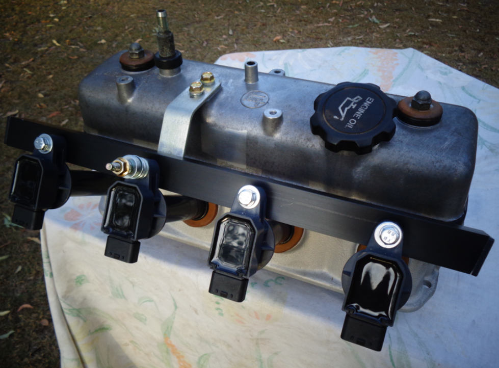
Should have the incremental rotary encoder arrive here this week, with a single "Z" pulse output, I can hopefully use as a CAS signal. I've decided to fit this dissy to my 4K-U engine in my KE-30, so I can do some real road testing on it, instead of on the 5K stationary test bed engine, in my workshop. I will need to change my single ignition coil over to COPs. I built a COP frame for the Denso COPs, a couple of years ago. It was a quick build in a couple of hours on a Sunday afternoon. That one is still in use on the Test Bed 5K engine stand. However, fitted to a road car, would require something a bit more rigid & strong, so I built one over the weekend, out of stock aluminium & few rivets & 6mm Riv-Nuts from Bunnings. It is quite rigid; as I pick up the whole head's weight, holding onto the aluminium bracket. Those two flat bar angled brackets from the rocker cove, are actuallt stainless steel. Just awaiting some DENSO 4 wire plugs for the COPs, so I can wire them all up. I hope to be able to feed the 3 wires to each COP, through the aluminiun channel, to keep it neat & out of sight. I've purposely made the COP mounting frame a little longer at each end, on purpose. It maybe; that on the engine, the frame vibrates a bit at a particular RPM, that might coincide with a resonant frequency of the frame & it's mounting brackets. If that eventuates, I can always run a couple of support bars down from the ends of the COP bracket, to the engine block below. Cheers Banjo


-

A Must Watch for Every Toyota Enthusiast
Silent Icecream replied to Banjo's topic in KExx Corolla Discussion
That was a very interesting watch. Thank you for the recommendation. -
Well, I've cracked out the stripper wheel to have a look at what's under some of the paint, and in a few spots the answer was "rust" so I feel entirely vindicated in being a bit aggressive. I also discovered a nice lump of bog around the front curve that I'd not paid attention to earlier, and under that bog? Also rust. Still feels quite doable. I'm debating how difficult it will be to get the frame de-skinned, which is feeling like the best way to make sure I get it out completely.


-
Hi All, I'm not into AI as yet, as I have enough on my plate each day, to keep me very busy. MicroSoft has added AI to a number of their products. I use MicroSoft WORD every day, in my business. The latest update of Word, includes an AI function called "Co-Pilot". Basically, You ask it to produce/write something about a particular subject, & it goes away, & in a very short time, will come back, with something it has created, based on it's scouring the web, & other resources at it's disposal, where it can "learn" about what You have asked it to do. So, I'm interested in upgrading older engines, with modern day ECUs, & precision control. Of late, I've been really investigating crank & camshaft triggering systems, & currently experimenting with using a incremental rotary encoder, installed inside a gutted dissy, (thanks Taz-Rx), to produce equivalent crank & CAS pulse for a Speeduino ECU. So in Microsoft Word I simply gave Co-Pilot this task . . . . . "Write an article on using an incremental rotary encoder as a triggering system for an automotive engine" Within about 5-10 seconds, Co-Pilot produced the following short discussion, about this subject (see below) _________________________________________________________________________________________________________________________________________________________________________ Incremental Rotary Encoder as a Triggering System for Automotive Engines Innovative Solutions for Precision and Efficiency Introduction The automotive industry has seen exponential growth and technological advancements over the years. One such innovation is the use of incremental rotary encoders in engine systems to enhance performance, precision, and efficiency. This article explores the application of incremental rotary encoders as a triggering system for automotive engines, highlighting the benefits, functionalities, and implementation methods. Understanding Incremental Rotary Encoders Incremental rotary encoders are electromechanical devices that convert rotational motion into digital signals. These encoders operate by generating pulses in response to movement, which can be used to determine the position, speed, and direction of a rotating shaft. The working principle involves a disk with evenly spaced markings and a light source paired with a photodetector. As the disk rotates, the photodetector reads the markings and converts the interruptions into electrical pulses. Types of Incremental Rotary Encoders There are several types of incremental rotary encoders, each suited for specific applications: · Optical Encoders: Utilize light sources and photodetectors. Known for high precision and resolution. · Magnetic Encoders: Employ magnetic fields and Hall-effect sensors. Suitable for harsh environments due to their robustness. · Capacitive Encoders: Use capacitive sensing technology. Offer good performance with low power consumption. Application in Automotive Engines Incremental rotary encoders can play a pivotal role in enhancing automotive engine performance by providing accurate and real-time data on engine components' positions and speeds. Here’s how they can be effectively utilized: Triggering System for Engine Timing Engine timing is crucial for optimal performance, fuel efficiency, and emission control. Incremental rotary encoders can serve as excellent triggering systems for engine timing by: · Crankshaft Position Sensing: By measuring the crankshaft's position, encoders can ensure precise ignition timing and fuel injection. · Camshaft Position Sensing: Encoders can monitor the camshaft's position to synchronize valve operation with piston movement. Speed and Direction Monitoring Incremental rotary encoders can provide real-time data on the rotational speed and direction of various engine components. This information is vital for: · Engine Control Units (ECUs): ECUs can adjust engine parameters based on the data received from encoders, optimizing performance. · Diagnostics: Encoders aid in diagnosing issues related to engine speed and direction, facilitating timely maintenance interventions. Implementation in Automotive Systems Implementing incremental rotary encoders in automotive engines involves several considerations to ensure seamless integration and optimal functionality. Selection Criteria Choosing the right encoder depends on various factors: · Environmental Conditions: Opt for magnetic encoders in harsh environments due to their durability. · Resolution Requirements: Optical encoders offer high resolution, making them ideal for applications requiring precision. · Power Consumption: Capacitive encoders are recommended for systems where low power consumption is crucial. Installation and Calibration Proper installation and calibration are essential for the accurate functioning of encoders: · Mounting: Encoders should be mounted securely to prevent vibrations that could affect signal accuracy. · Alignment: Ensure that the encoder's disk is aligned correctly with the light source or magnetic sensor. · Calibration: Regular calibration checks are necessary to maintain optimal performance and accuracy. Benefits of Using Incremental Rotary Encoders The adoption of incremental rotary encoders in automotive engines offers several advantages: · Enhanced Precision: Accurate measurements of position and speed lead to improved engine timing and performance. · Real-time Data: Immediate feedback allows for timely adjustments and diagnostics. · Reduced Emissions: Optimized engine operation can contribute to lower emissions and better fuel efficiency. · Cost-effectiveness: Improved diagnostics and maintenance reduce long-term operational costs. Challenges and Solutions Despite the benefits, there are challenges associated with integrating incremental rotary encoders in automotive engines. These include: · Signal Interference: Electrical noise can interfere with the signal. Shielded cables and proper grounding can mitigate this issue. · Mechanical Wear: Continuous rotation can lead to wear and tear. Regular maintenance and high-quality materials can reduce this risk. · Temperature Variations: Extreme temperatures can affect encoder performance. Choosing encoders with suitable temperature ratings can help. Conclusion Incremental rotary encoders are revolutionizing the way automotive engines are monitored and controlled. Their ability to provide precise and real-time data on the position, speed, and direction of engine components makes them invaluable for optimizing engine performance, enhancing fuel efficiency, and reducing emissions. By understanding the types, applications, and implementation methods, automotive engineers can harness the full potential of incremental rotary encoders to drive innovation and efficiency in the automotive industry. _______________________________________________________________________________________________________________________________________________________________________ Next time I might ask it a question a little bit harder . . . . . like "How do You remove the camshaft sprocket cover, on a Toyota K Series engine, without removing the sump ?" Cheers Banjo
-
Hi John, Things are looking up, & possibilities with the guard & bonnet. To make You keep feeling good about your project, I suggest You have a look at this Corolla waggon, still in daily use in South America. It's a tradies daily drive ! https://www.curbsideclassic.com/blog/cc-capsule/cc-outtake-1977-toyota-corolla-wagon-one-hard-working-corolla/ Enjoy ! Cheers Banjo

- Earlier
-
 Trent Latham joined the community
 -
 Jabbar Ramih joined the community
 -
A brief update, I caught up with Pete and now have a replacement bonnet and left guard. They'll need a bit of work. The bonnet skin looks like it's been separated from the frame and sprayed at one point, but I need to dig a bit deeper and get a good look. The adhesive isn't, so it's separated out a bit. It looks pretty straight though. The guard has two points of rust through, inside near the light and through the outer shell bottom near the door. It also has some bog in it near the blinker. Dad has sourced some tyres for me to help move it around. It's got YR 78 S12's on it and they are clearly toast so he's putting some second hand 165-12's on just to move it around. He's also getting the rims sandblasted and painted for some beer money. I expect that to be the only activity that doesn't cost me money. Also included, the two workshop manuals that were located in the boot of the car. The Scientific Publications one had absorbed so much cigarette/cigar smoke that I think I'm still coming off the nicotine high from touching it.


-
 Rjaycamilo joined the community
 -
 Willsy joined the community
 -
 Galantman74 joined the community
 -
twin 40dcoe on a 1.6 with extractors and electronic ignition or dizzy conversion from points is awesome, I fitted that to my 1977 galant 4g32 1.6
-
He has a repairable bonnet and left guard. I'm dropping in on Monday (last week was just a bit too busy). Fortunately I think I have the chrome trim from the old one.
-
Yesss, I'm watching zoro anime and one piece series
-
 jackkieew joined the community
 -
How did you get on with Pete?
-
 Kamlesh Aacharya joined the community
 -
 revscheck joined the community
 -
Thanks Banjo, I'll add those to my "Inspiration" folder. Looking at the rear windows I'd say these are all station wagons rather than vans. I honestly don't know how my grandfather got the smaller windows in. I do know the wood paneling was made by the carpenter at Rowntree-Hoadley (now Nestle) where my parent's both worked. Does anyone know what the difference in grille is about? Is it simply that the deluxe version had a centre channel with the logo where the regular had a sort of floating logo? The one I have has the centre channel, but dad has reminded me a few times that it's not the original. Somewhat related, the Toyota Centre for Excellence (what used to be the Altona factory) has a mint condition KE10 in the museum/collection located in the old Powertrain building. Unfortunately not generally available to the public though.
-
Hi John, Just to inspire You, here a couple of pics of a couple of restored E10 Corolla 2 door waggons I found on the net. Enjoy ! Cheers Banjo


-
I went out in the shed tonite, & found a 3K early dissy, which had the narrow, yet deep main body. This dissy was in very good condition, but I gutted it completely, so I could determine, if the incremental rotary encoder, would sit neatly inside. Ah Yes ! I even found a jam jar lid, in my wife's kitchen cupboard, (She is out tonite) that fits perfectly, like it was made for it. I would have liked a dissy body, with a replaceable ball race bearing at the base; like the one in the 4AGE distributors, instead of the phosphor bronze ones fitted to all K series engines, I believe. However, this dissy shaft & sleeve bearing are in remarkable condition, so very happy with the fact, that the two parts, manufactured, many decades apart, are so complementary. Just have to be patient now, until the Omron incremental rotary encoder, with a single "Z" pulse per revolution arrives here, & I can take it to the next stage. Cheers Banjo


