

drift freak
-
Posts
265 -
Joined
-
Last visited
-
Days Won
4
Content Type
Profiles
Forums
Events
Gallery
Blogs
Everything posted by drift freak
-
Seabiscuit - after alot of persuasion from Jordain I finally decided to use a ke20 xmember. It worked out heaps easier to install everything. I also spoke with a different engineer (a friend of a friend) and he has no worries passing it with the the 20 one. I think it really just depends on who you talk to as to what is safer (heaps safer to have direct bolt in lca's than have brackets made to adapt them). Using the 20 xmember instead allows a direct bolt in of the lca's but the engine mounts are a little trickier to fabricate. It also sits the motor lower and suits the sump position very well. To be honest it looks alot more standard now than it did with the ke10 xmember that's for sure :)
-
Thanks 13BT_ke20 yeah I'm pretty sure I can modify it as I already have to reshape the front edge of theguard because the tyre scrapes. Weldon is a funny thing, it's all in the preparation, making sure it's clean and bare metal are the key. I've only tacked most stuff in as I'm gunna getthe shell fully sand blasted. Then I'll repair the rust and fully weld everything up including stitching the shell :)
-
Oldie, I just re-read your post. Wheel well. Maybe it would be possible but it will hav to wait until everything is in and sorted, don't want to lose any suspension movement or lock.
-
Little red spirit - maybe a workplace accident with the ride on is in order, trim my feet to appropriate size and also get enough money to finish it ASAP. LOL. I think with small shoes and some practice it will be fine.
-
Oldie, do you mean the gear box tunnel (notchin??) the tunnel is pretty tight against the gearbox so there isn't much room to do anything unfortunately. Was thinking maybe an auto instead???????
-
So I've made some more progress peeps. I spent most of Sunday working on the central floor brace so I could put my seats back in and start sorting out the steering column setup. I folded, cut and welded a piece of 125mm*75mm*3mm box tube into place then made up adapter tabs to install the seat braces. I have now welded the drivers side mount back in and reinstalled the drivers seat, along with the steering column. I am pretty stoked with how everything fits apart from the lack of foot space in the drivers footwell. So as you can see things are extremely tight so it will be race shoes only while driving or barefoot LOL. So now the drivers seat is in, I will taking the old girl to a local hotrod shop next Tuesday to have the steering rack professionally installed. Until then I will concetrating on the fuel tank enclosure in the back. I would like to get it covered and fuel lines setup. Oh another shot :) Thought Id put up a shot of roughly how the dash will be setup, very simple but I think it will look smick once its all in there and finished.


-
Cheers wrathchild, it's finally starting take shape. After so many different combinations it rolls, sits nice. Now for steering and brake pedal setup.... To be continued.....
-
Finally got the old girl rolling today. It had been way too long. Once I'd gotten over the fact that it was rolling I pushed her back in the shed (for some more photos) Then i got stuck into making the floor brace piece. Still going with that.


-
Well I spent yesterday banging round in the shed and made some more progress. I re-fabbed the fuel cradle to give me some extra room for the exhaust. Then I made some lowering block from 50*50mm box tube. These are quite easy to make, I drilled a 12mm hole through both sides for the locating pin and then reamed one side out to 14mm to suit the locating pin on the spring. Then I got stuck into re-making the centre floor brace so I can put some seats in the front again. Man this is a slow task as it requires cutting and grinding until the folded brace sits nicely over the tunnel. Below is the first mock up I have attempted. I will be getting some more tube but painted instead of galvanised for the final version. I also got a couple of under carraige shots for those interested in the suspension layout. So as you can see things are moving along nicely. i am pretty happy with how it is all coming together. Once the fabrication work is finished it will be onto the body for rust repairs, then paint and interior :)


-
Looking good jordy, gettin super keen :)
-
Just some more photos of the brakes on. Now I need some wheel nuts to pull the studs back through and then I can fit some wheels and look at setting the ride height in the back :) Prgress is finally starting to come together, it is at the most complete stage since I bought the rolling shell nearly a year and half ago lol


-
Well I've made some more progress in the last couple of weeks. I received my inlet manifold from Glenn (Celica RA 45) so I have now installed my blacktop quads and set up the temporary linkage system. I will have to sort something out in the future as the linkage fouls on the rocker cover and is in the way of the rocker breather hoses. Glenn has a centre pull linkage setup from underneath for sale but I will try and make my own first. Next will be sourcing some velocity stacks and air box. Although I will probably have to make a custom box as it sits so close to the firewall at the moment. I was surprised as the TPS plug from the Beams loom plugged straight into the quads TPS plug. Bonus!!! No I have also had my EF XR6 LSD diff cut down and axles sent for resplining. I have mounted it on the rea leaf springs using Kustom Bitz mounts I purchased directly from Kustom Bitz in Victoria. I am yet to weld the mounts on as I need to see if the diff rotates at all once it is on the ground with the wheels on. I also need to have the wheels back on to help locate the diff centrally (equal space between wheels and guards) Hope full some more updates soon with my axles expected back this week :)


-
Yeah I know Jordain. Once it's all in their and the leafs are flattened I reckon there will be enough room to get it past :) I probably wouldn't have made it so wide if I did it again but too late now :)
-
So a bit more progress in the last few days. I decided to make a start on the boot setup to include my fuel system. I have a 60L alloy fuel cell with Carter low pressure lift pump, surge tank and Bosch 044 EFI pump. Just need to get some fuel hose and fittings and get it mounted. So I started with a hole in the floor from the previous owner Then I decided I'd like to only sink it into the floor as far as the original spare wheel well. I made a frame to mount everything into I then cut the floor to suit the frame size. After cutting the floor I realised I probably should have tried to compact it a bit more because I haven't left alot of room for the exhaust to run passed it. With it trial mounted in the floor it all looks pretty good and fits snugg. Now to just sort a few bits and pieces out and wrap the underside in sheet metal to seal it all up. As you can see I have mounted it a little toward the drivers side, this is to try and distribute the weight. I will be installing the battery enclosure on the passenger side to add some more counterweight. Any opinions?????


-
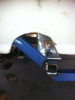
Well a little more progress the other day. I have now re-mounted the engine on the KE20 xmember. Must admit it took a little more than I expected but in the end wound up coming together really neatly. Where my engine was positioned from the old xmember (I didn't undo the gearbox xmember as this located it second time round) the 3SGE engine mounts clashed with the KE20 xmember. I had to cut the little locator pin off the mount (stops the mount spinning on the engine brace. I wasn't too worried about this as now its mounted in the xmember it can't spin anyways. I used 3mm mild steel plate to fab the engine mounts. So stoked with how its finished up as the cam cover now clears the horizontal line from either guard :) This is another pic of how well the ea chaser sits in the front guard with -4 deg camber. can't believe how good it fits :)
-
Well a little more progress the other day. I have now re-mounted the engine on the KE20 xmember. Must admit it took a little more than I expected but in the end wound up coming together really neatly. Where my engine was positioned from the old xmember (I didn't undo the gearbox xmember as this located it second time round) the 3SGE engine mounts clashed with the KE20 xmember. I had to cut the little locator pin off the mount (stops the mount spinning on the engine brace. I wasn't too worried about this as now its mounted in the xmember it can't spin anyways. I used 3mm mild steel plate to fab the engine mounts. So stoked with how its finished up as the cam cover now clears the horizontal line from either guard :) This is another pic of how well the ea chaser sits in the front guard with -4 deg camber. can't believe how good it fits :)


-
Jimi91 : Yeah we aren't totally sure how all this front end is going to work out until we actually drive it on the road. Its pretty much unexplored territory in the KE1* so we will wait and see I suppose.
-
Hmmm interesting. I don't think they bind but will check today to make sure.
-
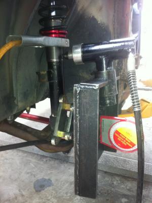
So yeah we had some good results with the strut bender yesterday. I was a little sceptical when Jordain first arrived with it but it worked quite well. As you can see from the following photo it is quite simple. I was using the tool in this configuration because I had added too much camber and needed to reduce the angle. To add camber the hydraulic ram is pointed away from the car and a chain wrapped around the strut and the head to bend the hub inwards. I didn't get a good photo of this, sorry. The only issue I now have is how much King Pin Inclination it has added to the geometry. This is shown in the following photo. As you can see the level shows the straight line through the strut tube to the ground and how far the king pin is inclined over. What we did was measure the backspace from the where the rim bolts up to the rear edge of the rim and then when we bent the hub towards the strut we just allowed enough clearance for the coilover kit and tyre bulge. This gave us enough camber but maintained clearance for everything. Next time I do this (if I need to again??) I would only bend the stub enough to gain the correct angle and also try and maintain the original king pin angle. Definately a step in the right direction though. Question can anybody provide some feedback on the new king pin inclination??? Will it destroy the ball joint real quick like this??? Is there any way I can fix it without straightening the strut???
-
So yeah we had some good results with the strut bender yesterday. I was a little sceptical when Jordain first arrived with it but it worked quite well. As you can see from the following photo it is quite simple. I was using the tool in this configuration because I had added too much camber and needed to reduce the angle. To add camber the hydraulic ram is pointed away from the car and a chain wrapped around the strut and the head to bend the hub inwards. I didn't get a good photo of this, sorry. The only issue I now have is how much King Pin Inclination it has added to the geometry. This is shown in the following photo. As you can see the level shows the straight line through the strut tube to the ground and how far the king pin is inclined over. What we did was measure the backspace from the where the rim bolts up to the rear edge of the rim and then when we bent the hub towards the strut we just allowed enough clearance for the coilover kit and tyre bulge. This gave us enough camber but maintained clearance for everything. Next time I do this (if I need to again??) I would only bend the stub enough to gain the correct angle and also try and maintain the original king pin angle. Definately a step in the right direction though. Question can anybody provide some feedback on the new king pin inclination??? Will it destroy the ball joint real quick like this??? Is there any way I can fix it without straightening the strut???

-
Yay back on board mate, nothing like a bit of reading to inspire you huh??? :) I will prob try and come up at some stage soon and visit Jordain and your self one weekend maybe. Great to here things are still progressing though that's the main thing.
-
No worries Dave. Whenever your in town just call. Wouldn't mind another opinion :)
-
KE25 nut : If you had original springs that are large diameter and have now gone to small diameter coilovers you wont have any problems adjusting some more camber into your front end :) worst case bend your struts a little bit and adjust your camber tops back in. Heaps better for overall adjustment because your can go both ways with fine tuning. I think a gusset like in the photo,these are technotoy tuning's version, it runs from the stubaxle/spindle to strut tube.Probably a very good idea after stressiong the stub axle/tube joint in the bending process.

-
Ke25 nut: thanks for the info. Yeah the kmac centre bearings are fully replaceable direct from kmac. One options is a urethane mounted spherical bearing which I presume is to try and eliminate impacts into the strut tower itself and extend bearing life. Jordain had some positive results yesterday with the strut bending tool he acquired from somewhere in Sydney. He is coming down to my house on Sunday so we will get some photos of the process and post them up. He is stoked with his results and now his front end is pretty well sorted :)
-
Awesome thanks :)


