

drift freak
-
Posts
265 -
Joined
-
Last visited
-
Days Won
4
Content Type
Profiles
Forums
Events
Gallery
Blogs
Everything posted by drift freak
-
Good work!!! Got any vids of the new engine??? Which adaptronic are you using???
-
LittleRedSpirit - Yeah it idles pretty well for now. I was lucky enough to get a ecu config file from a guy in Berridale who I met online (massive props T. Duncan for sharing his tune with me). It has saved me a hell of a lot of work but it still needs fine tuning on a dyno to sort out all the fiddly settings and stuff. It will do for now to move it around though. Not entirely sure about the brake system, I think I might need to put in boosters as the pedal is fairly stiff. It does stop reasonably well though so I need to borrow my mates brake testing machine and get some stopping g-force readings and pedal pressure figures, this will allow me to determine whether the booster is needed or not in relation to the RTA braking specs. Hopefully I can sort this in the next week or so......
-
Damn I wish I had a pool. I can't complain to much though I have a river 5min away and the ocean is 15min.
-
Wow your wagon is smick! Nice work 👍 yeah I'd be lost without my shed plus it gets me out of the fiancé's hair lol
-
Cheers b.l.z bub, yeah years of overtime and no social life got me the shed. Definitely wouldn't have started such a massive project without it.
-
So I finally had my brake flare tool arrive the other day and have since put the brake and clutch lines together. To be honest buying the Eastwood Brake Flare Tool was easily the best tool purchase I've ever made. I got it out of the box and within minutes was creating perfect flares for what I needed. So now the coupe drives and stops which has put a massive smile on my face and has made my xmas/new year just a little less stressful. Check it out So now its time to start stripping it back to pieces and start finishing the body and get it ready for paint. Watch this space :)
-
I've got an EF XR6 LSD disc brake diff in mine but it might be a bit big for what you want. I needed the stud pattern so it was a simple choice. I also have a Nissan Pintara (4.11:1) disc brake rear end for sale complete end to end, will get measurements if your interested (might need cutting down, not sure). Cheers
-
Yeah cheers for the heads up :) I will be grabbing myself a set of tube spanners ASAP. Like you said they are totaly invaluable as I've come to realise!!! I just wish this flare tool would hurry up and arrive, I have some time off over the new year and want to get this done.
-
So how did you get them to seal properly??? Did you just tighten and loosen a few times to create a good fit??
-
Ah such a pain in the arse!!! I should have given myself a little more clearance behind the pedals as its almost impossible to get the spanner on the firewall bulkhead nuts. A few people hav said the same thing about tightening them a few times to ensure good sealing. Very frustrating part of the build that's for sure
-
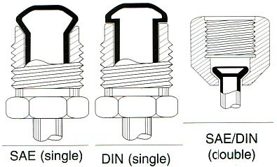
So I have made some more progress but man its frustratingly slow. I got all the front brake lines made and installed, clutch line connected and the rear line in up until the flex line to the diff. I am currently using a SP Tools brake flaring tool and have found the flares extremely hard to make with a consistent finish that wont leak as the steel lines are extremely hard to flare. This tool would probably work fine on copper or aluminium tubing but not steel or stainless. Anyways I tried to bleed the system using the existing lines with temporary flares and it just leaked fluid striaght out of the back of the m/cylinder. After a bit of research I found this diagram on what flare suits what fittings. So I have decided to bite the bullet and buy a good flare tool from the states, cost a bit more than I would have liked but I'll have it forever so its a bit of a trade off. After all the muckin around I got the lines bent up so I now have templates to follow when I go to make the final lines. So for now I'll be removing the motor, gearbox and driveline, heater unit and the dash and will try and get the rust and the rest of the welding sorted then once I have the flare tool I'll finish the lines and get it driveable.


-
Yeah for sure but this car has broken me. Need to save FML!!!! Where's the lotto win when you need it!!
-
The pressure reg is after the fuel rail, mounted on the drivers side inner guard. If I move the reservoir to the front face of the strut tower there should be enough room for the air box but if I do this I still have to work out how I will fit the air box between the no.4 trumpet and the firewall, at the moment there is only 5mm clearance.
-
Hey Autofill, Yeah I know the reservoir is in the way but I will be making a custom housing to accommodate it. I am thinking I will either use 45mm straight or 90 curved to gain some room. I really only want to use the air box for rego inspections and if it get defected but leave them exposed during normal conditions. I have a friend who runs mesh between the TB and trumpet and fits a foam filter into the trumpet.... What are your thoughts?? Would this create too much turbulence and reduce performance. Worst case scenario I run braided line to the reservoir and move the reservoir next to the radiator on the drivers side of the radiator support (last option)
-
Well I decided to have a crack at the hard lines for the brakes this arvo. It was a challenge to say the least but a local brake guy gave me some really handy advice. He suggested that when I'm planning the lines I use some 2mm fencing wire to mock up the route so I don't waste any 3/16" tube. Awesome advice!!! So I started by putting the flex lines onto the calipers and mounting them to the strut and mounting tab on the body. I then mocked up the drivers side line with the wire then bent the tube to match the template. I used a SP Tools pipe flaring kit to flare the ends WITH THE TUBE NUTS ON (don't forget these as you will need to cut the tube to put them on after and the hardline will be too short). I found out how to flare the hardline by typing in 'double flare brake line' into youtube. End result looked like this The installed braided line looks like this In this photo you can see the splitter under the dash for left and right brakes, the centre outlet goes to the master cylinder I'll get some photos of the passenger side but its pretty much identical to the drivers side apart from it runs over the top of the firewall recess, its just a straight run for this then angled down once its out of the cabin and under the guard. After talking with Jordain a few weeks back I took his advice and drilled a small hole in the inner guard as seen in the picture below with no.1 pointing to it, this is to remove the front brake lines from the enigine bay as they used to go through the engine bay and come through the inner guard at the no.2 hole. This solves the major problem of routing the passenger side brake line up and over the motor, past the recess in the firewall. It would look really messy and just plain crap if it ran through the engine bay. So onto the under dash hard lines tommorrow arvo, these will be quite difficult as there is multiple bends to clear everything and only limited space.


-
Wow cheers feral4k!!! Thanks heaps, maybe next year????
-
So a bit more progress has been made in the way of running lines to the reservior from the m/cylinders and the hard lines. I tried to keep the fluid transfer lines as close to the actual rear brake and clutch lines as possible, this is just to hide them a little and clean up the engine bay. Due to the holes in the firewall being through the reinforcement bracket i have drilled them a little bigger so I can weld the sheetmetal together to increase the strength back to original. The hose is 14mm OD so I drilled the holes @ 16.5mm ID. Heres the pedals with the adapters attached, they are facing the wrong way in this pic as when installed they actually face toward the firewall. Heres one with the pedals installed showing how close they come to the wiper motor mount This next one shows the bulkhead fittings on the inside for the rear brake and clutch lines plus where the reservior lines fit through the firewall (still waiting on the front m/cylinder rubber hose) And one from inside the engine bay Now the following 2 give you an idea of how well things are hidden when the trumpets are fitted back up


-
Cheers lotec11 :) yeah I'm gettin keen as too. Thanks for the props
-
Sweet!!! Do you make them to suit blacktop quads????
-
Is this you Glenn??? I was chasing a timing belt and tensioner but got a genuine belt from Toyota for $84 so pretty happy with that. Do you have any dimensions for the air box, like how tall the air box is, how far it extends behind the last throttle body (toward the firewall)??? Also who made the curved trumpets?? They look trick :)
-
Yeah I'm gunna need to make some sort of filter box. Probably out of fiberglass maybe alloy sheet. Definitely will need to sort something out. Are those photos of a 4a???
-
Nisrola - not to start with as I have a friend with a similar setup with no booster and his brakes have great feel and don't need to much effort to get it to pull up. If it doesn't work all that well I will be putting a booster under each front guard (for front and rear) to fix it. Fingers crossed it works fine without it though, will be a massive pain in the arse to replumb it.
-
Ok so I spent the morning installing the brake switch and clutch/brake reservior. Pretty happy with how it all came together although there isn't much room for filter socks or manifold now. Not sure how I'll get around this issue but I'll sort that later haha. So I pulled the pedals out of the car and bent up the horizontal part of the bracket for the brake switch and drilled the mounting hole in it for the switch. I then cut and drilled the mounting plate that attaches to the pedal assembly. From here I bolted the mounting bracket to the pedals and measured the length of the horizontal piece + a few mm's just in case. Then I put the horizontal bracket into place ensuring the switch was activated when the pedal was in the relaxed position and welded it together. With this setup the switch completes the brake circuit when the pedal is pushed to the floor. So then I moved onto the reservior mount. I am a little confined as to where I could put this as the full level in the reservior must be above the master cylinder so the fluid will flow under gravity. I also didn't want to run hoses all over the engine bay so as close to the firewall was the neatest and most logical spot. Now I've seen Jordain's setup where he is going to move his wiper motor to allow more room for his reserviors on top of the m/cylinders but this presents its own problems of making sure the fluid doesn't leak out without being noticed in behind the dash and also the issue of remounting the wiper motor and making sure everything works as it should. First I made a template of the shape of the strut tower where I roughly thought the reservior was going to sit (doesn't need to be perfect as the welding process fills any small gaps). I then made sure this level was above the m/cylinders (as mentioned before) and cleaned the area up with a sanding disc ready for welding. I had a lower control arm from another diff laying around so I cut a piece from that and cut the shape out of it. Drilled some mounting holes and welded the nuts to the back of the mount. I then double checked its position with the reservior mounted to the bracket and tacked it to the strut tower. So it looks like this when finished


-
Sweet, easy fix :) got anymore photos??
-
Looking good mate, hey what did you find with your clutch fork???? Was it installed properly or was there another problem??


