Leaderboard


Popular Content
Showing content with the highest reputation since 05/16/26 in Posts
-
It appears to me; from your photos, that it may be, that the ignition switch itself is OK, but the plug in connector & socket that connects the ignition switch to the car's wiring harness, is corroded & unserviceable. I may well be, that if you cut off the plug & socket, & substituted another generic plug & socket; or simply connected/soldered the wires together, without the plugs & sockets; then maybe the car will work perfectly. As You have the ignition switch out; You could test that the contacts inside the ignition switch connect OK, with a simple multimeter, or a battery & test light. Even if that is a temporary measure, to get you going again; it would then allow You time to search UK, French & German ebay sites, & see if anything comes up when looking for Neiman ignition barrels. Even if You can't connect it up, without the plugs & sockets; then any good auto electrician, should be able to do that for you, & get You mobile. Cheers Banjo1 point
-
Do you think that was a factory part when the car was new? ..or has someone fitted a European ignition system to it afterwards? If you're lucky its a common Neiman part shared with other cars in the 80s, so you could get a second-hand one in good condition, or a new one from another one-make car club. There are Ferrari ones for sale... Do you know what America used? The column should be the same as yours. Which part do you desperately need, and can you substitute wiring and contacts from generic electrical parts? How's your French? https://mtparts.fr/product-categorie/japanse-tractor-parts/suzue/electrical-parts-suzue/1 point
-
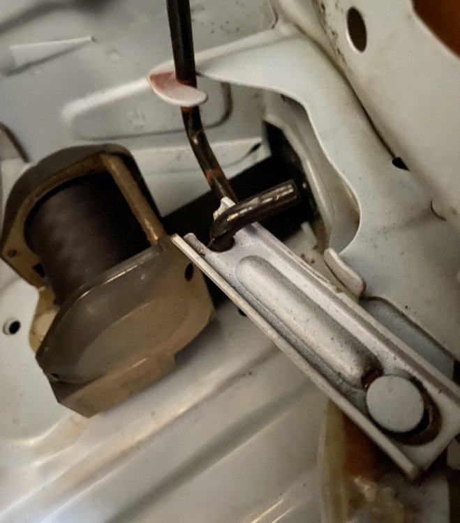
The plates are 80mm long x 23mmwide, neatly pressed from a flat maybe 30mm wide to roll the edges for strength. Open slot one end, closed slot on the pin end. Not an easy shape to make.1 point
-
The usual torsion bar spring used in the 70s.. and the other side... They can be quite grunty springs when you try and fit them!
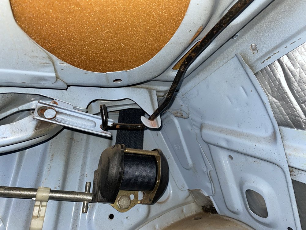
 1 point

