

Banjo
-
Posts
1933 -
Joined
-
Last visited
-
Days Won
95
Content Type
Profiles
Forums
Events
Gallery
Blogs
Everything posted by Banjo
-
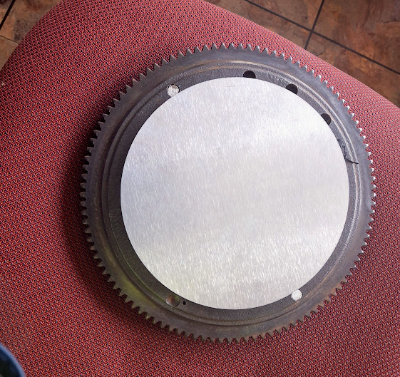
I'm currently, "experimenting" with building a "cam based" trigger driver, to provide CAS & crankshaft pulse trains; so that an ECU can quickly & easily be hooked up to any K Series engine, without the need for a stream of crankshaft generated pulses; from either the front crankshaft pulley, or the rear flywheel. When I attempted this, I looked around my shed, & could only find one of these "Australian Made" Bosch dissies. I have plenty of the olde narrower Denso dissies, that were fitted to the K series engines, both in points & VR sensor arrangements. I really want another of these larger Bosch dissies, for the K series; so if anyone has a spare one; & is prepared to part with it, & sell it; then please contact me, in this thread, or PM me. A couple of pics to show / demonstrate, that progress to date is good, & I'm pretty sure it will be " a goer". And yes; that above, is a jam jar lid, again ! The reason I need the wider dissy, is to accommodate the largest alumium disk to fit a ring of rare earth magnets. P.S. "Not a rotor button, Spark plug lead cap, or set of points in sight" Cheers Banjo


-
Hi Kayzz, How are you going getting all your bits together for this engine ? Would love to see some pictures of the kit, if You can post them. Cheers Banjo
-
Hi Kayzz, That must be a new dissy, that You've pulled to pieces, as it is pretty clean ? It is looking like You might have to await One Six industries, to produce their suitable dissy, for your modified 4K-U engine. Your STM Pro ECU, will need two (2) electronic inputs. A CAS single pulse, & a stream of crank or camshaft pulses, to provide crankshaft speed & position. The aftermarket physically large dissy I saw on the internet, suitable for Toyota forklifts, fitted with 5K petrol engines, is not what it seems. Because it labels it as suitable for Toyota forklifts with electronic ignition, I "assumed wrongly", that Toyota had fitted an ECU to these later model fork lifts, & therefore needed a upgraded distributor, with CAS & trigger wheel outputs. Wrong; I was fooled by the apparent size of the distributor, assuming it had a CAS & trigger wheel, of some kind enclosed. When I look at the picture again, I realised it has a vacuum bellows on it, which indicated it has mechanical automatic advance/retard therein. On top of that the lead coming out of the distributor has a connector with only 2 wires, when I blow up the picture. That indicates, that it does not have an inbuilt CAS & trigger wheels. It would have 4 wires, if it produced CAS & trigger wheel pulses. Sorry, to get your hopes up, but it is back to square one, or await for One Six Industries, to produce one. Alternatively, You can build a simple CAS signal into the dissy you have, as Alteezaclub has suggested, but the crank trigger pulses would maybe best delivered by a crank mounted toothed trigger wheel, or maybe flywheel, as I have also mentioned. I haven't looked up the specifications for the STM Pro ECU, to see whether, it can accept crank trigger position pulses, generated by the camshaft. Have You confirmed that previously ? I have no experience whatsoever, with this brand of ECU. P.S. Did You buy this STM Pro ECU kit new or second hand ? I read somethwhere about these being in a kit form, that You have to build yourself. My current suggestion is; that whichever way, You ultimately go; You will need a CAS signal, if You are set on running this engine, in sequential injection & ignition. You should convert this dissy in your hand, to a CAS pulse output device only. All You need to do, is follow Altezzaclub's suggestions, of creating a single tooth off the main shaft, & pick it up with an appropriate Hall effect sensor. You could cut all those pins off on the spinning base plate; including the centre shaft, & fit a rare earth magnet, with it's South pole facing vertically, at the top. Then refit the plate, with the two (2) screws in the case, & drill a hole in the plate, in line with the magnet pole, to mount the Hall Effect sensor vertically through the plate. The Hall Effect sensors are cheap & available, & most sense a south pole, & are mounted in a threaded tube, so are easy to adjust, so you have a gap of 1-2mm between maget south pole face, & hall effect sensor face. N.B. Don't try to cut any of those pins off, without removing the shaft assembly from the disributor body. You will have to remove the roll-pin, in the "gear", at the very bottom of the shaft, so You can push the shaft up, & out of the distributor. Alternatively, You could cut off 2 off the three steel posts, & leave the longest & furtherest from the centre, & sense it with a Hall Effect sensor, that sensor iron metal, rather than a magnet pole, like below. ebay listing for Hall Effect Sensor Hall Effect Sensor Cheers Banjo


-
H Kayzz, I've been thinking about your issue & ignition/distributor needs, & what Altezzaclub has advised. Have a look at this link, here on the RollaClub website. https://www.rollaclub.com/wiki/index.php?title=Tech:Engine/K_Series/Electronic_distributor This is the base distributor You require, which is larger in diameter, than the other 5K electronic dissies. The chances of You picking up, one of these, in good condition; is about the same chances of winning the lottery. These were specifically manufactured for the 5K engines, utilised on Toyota forklifts. I have noticed on ebay, that there appears to be a replica of these dissies, produced; although I haven't been able to find a local ebay seller, stocking them in Australia. It would have to be purchased from an ebay seller in China. The reason these have come to be; is that the 5K Toyota engine, is greatly "prized", in S.E. Asian countries; but particularly, Malaysia & the Phillipines, where they fit them in mini Jeeps, & in Malaysia they power racing water canoes. https://www.youtube.com/watch?v=PbGLWHxeru0 One is going to set You back, about AUD 300, but You will get a base component with new bearings, cogs & seals; which will cost You money if You purchase or find a second hand one; & then have to source all the bits to recondition it; even before converting to a CAS & cam/crank trigger wheel. ebay 5K Electronic Distributor for 5K Forklifts Hope that gives You another alternative. Cheers Banjo

-
Hi Kayzz, I don't have the luxury of a machine shop, or even a small lathe (but I do wish); but there are lots of things You could try, with basic hand tools. The photo above is of a K Series dissy; although it is the wider one, originating from Bosch, rather than Denso. You can see from the picture; that once You strip out the top plate, & all that is mounted on it; it gives You plenty of room, to create, a single protrusion, to create a CAS pulse, with a multitooth wheel above it. This was an experiment I tried a few years ago. I mounted a single "rod" rare earth magnet, on the spinning plate. Over the top of that, I mounted a piece of printed circuit board, with four (4) off Hall Effect sensor elements, that picked up the pole of the magnet, spinning below the circuit board. It worked well, & operated like as an "electronic rotor button"; as it switched four seperate ignition coils, on & off, to their respective spark plugs. I ran it in my KE-30 for about 6 months, & it worked perfectly, in co-ordination, with a Jaycar programable ignition module. The simplest way, would be as Altezzaclub has suggested, with a multi-toothed wheel, mounted above the single tooth CAS tooth. If you've already got a K series dissy; You just need a later model dissy, from a 4AGE or MR2; that you can grab the toothed wheels, & fit them to the original K series dissy. Using the dissy arrangement, means You don't have to fabricate a dummy shaft, to drive the oil pump. Cheers Banjo


-
The bulk of the Denso K series distributors were quite small in diameter, as they only had points in them; & certainly wouldn't have the room, to transfer the tooth metal wheels across, from the MR2 dissies, & similar; even if You did have access to the lathe, & cutting equipment to make it all go together. The exception was the Bosch dissy, from K Series engines, which was much larger in diameter , than the Denso model, which is quite "narrow". It is the Bosch one, I am going to try to fit a flying magnet disk inside. My dissy, is not for sale. The one I depicted, does not even belong to me. I have been assisting a friend of mine, here on RollaClub. Even if You decide to not use a gutted dissy; You will still need to make up a dummy shaft & cap, to fit in the dissy location point; to drive the oil pump, directly below the distributor. Olde K series Denso dissy cut down, & a dished Welch plug, sealing the top of the shaft. Have you considered just putting a commercially available trigger wheel, on the front crankshaft pulley ? Cheers Banjo

-
There is a growing pool of engine fans, who are resisting the use of the camshaft, for producing really accurate engine timing, despite the fact, that all early engines, worked this way; as the dissy was directly driven from the camshaft. The crank is the by far, the more stable way to create timing information that is constantly changing. However, there is some resistance, by those that are engaged in some forms of motor sport; like rallying; that the crank pulley trigger disks etc, are too prone to damage from road debri being thrown up into this area. There is however, another way, which involves placing the trigger wheel, on the rear of the flywheel, where it is totally protected. Funny, when I first started this Timing Accuracy journey; I tried counting starter teeth on the flywheel, until I discovered, there was rarely a flywheel, with the number of teeth, equally divisible into 360 degrees. However, fitting rare earth magnets to a aluminium plate, in behind the flywheel, is a very protected area. I've just received a large alumium disk, to which I will fit 36 off, rare earth magnets, & it will be installed into the rear of the flywheel. The Hall Effect sensors, will be mounted behind the sump, through the large steel plate, between the bell housing & the rear of the engine block. I've mocked it up, in cardboard, & it will all work well. Just got to get the disk & flywheel machined, & it will be a very stable & accurate way of producing rock solid crankshaft pulses , for the ECU, & leave the lower front of the engine, complete unmodified & molested. Cheers Banjo

-
Where in "the world" are You located ? My guess is the USA ? Is the 4K engine with 7K EFI already in a vehicle ? Are You doing; or have done a COP conversion ? Have You already sourced an aftermarket ECU ? Sorry about all the questions, but I'm trying to create a picture in my mind, where You are at, with this project. Pictures please, as they tell a thousand words. P.S. I've never had a Gilmer drive, but I hear they are pretty noisey ? P.S.S. I've just looked up Endeavour Engineering, & they are in Sydney, but are a construction company. Cheers Banjo
-
Hi Kayzz, So correct me, if I am wrong; but it appears You have a standard 4K engine, & have been lucky enough to get hold of all the EFI gear, from a 7K 1.8L engine, which You will fit to the 4K engine ? That's how I started out on this little project, & I have a 4K engine here, already on a stand, with all the EFI gear all mounted. However, I love the 5K, for it's ability to rev more freely, than the 7K, which was really developed by Toyota, for commercial vehicles. I currently have a 4K-U engine in my model KE30 2 door sedan. The 4K-U produced almost as much horsepower as the 5K, if you look at the specs in the mamuals. What particular 4K engine do You have ? What is the subscript letter after 4K ? The dissy, I depicted at the end of my earlier post, showing the dissy Altezzaclub & I have modified for his 4AGE engine, is a different dissy, to that, fitted to the the K series engines. I actually started out modifying the 4AGE dissy, by experimenting with a aluminium disk inside with embedded rare earth magnets, around the periferal, of the 70mm dia. disk. The only way I could fit them all in, & get 36 pulses per camshaft revolution; was to use assymetrical rare earth magnets. It got a bit too hard at the end, & we were running out of time; so reverted to counting the teeth in the existing 4AGE dissy iron teethed wheels. I still aim to try & build a dissy with 36 magnets fitted to a spinning aluminium disk, for a K Series engine. Strangely; it was only this morning, that I grabbed one of the "larger" Bosch distributors, that were fitted to some K series engines. From the photos below; You can see that not only, will the 70mm dia. disc fit; but it will sit low inside the dissy, which will provide room, for mounting two Hall Effect sensors, directly above the disk. It's early days, with that project, but after today's measurements, I'm pretty sure it is going to be possible, if I can sort out the issue of turning the Hall Effect sensors on & off; with the rare earth magnets, so relatively close to each other. P.S. Where about are You located ? If You are anywhere near Brisbane, Qld. , You are welcome to call by, & take a look, & discuss, what is possible. The photo below, is of said 4K engine on stand, with all the 7K EFI gear already mounted, & a COP cenversion. Cheers Banjo.


-
Welcome aboard, & thanks for your query. You've obviously read my thread above, in which I have experimented with several positions for the CAS signal generation. You can actually run the engine, in "wasted spark" mode (1&4 - 3&2), where you don't actually need a "CAS" signal at all. However. if You are wanting to run the engine in sequential mode ( firing order 1-3-4-2; then You will need the CAS signal. It only has one "purpose in life"; to tell the engine management system (EMS) or electronic control unit (ECU), that the next cylinder to be fired is no: 1 cylinder. This signal must occur after cylinder 2 has fired & before cylinder 1 is fired . A commonly used position, is somewhere between 90 deg & 60 deg B.T.D.C No: 1 cylinder. After reading my thread above, You can see I experimented with the CAS in several spots on the engine. As I was ultimately going to be running injectors, rather than a carby; I modified an olde fuel pump, to produce a single pulse per camshaft rotation, from the single fuel pump lobe on the camshaft. This worked, but the camshaft fuel pump lobe was not in the ideal position, to the opening in the block, for the fuel pump CAS option. Another idea, which again worked; was to add a rare earth magnet to the camshaft sprocket, & pick the magnet's presence up, with a Hall Effect sensor mounted through the camshaft sprocket alloy cover. This worked perfectly, & provided an LED built into the Hall Effect sensor, which made it easy, to determine the number of degrees before TDC No: 1 cylinder, that the CAS signal arrived, as this figure is always needed to setup up the ECU or EMS controller, in sequential mode. Ultimately, I didn't use this position, as if You ever have to access the magnet on the camshaft sprocket, it is a P.I.T.A., to get the camshaft sprocket alloy case off; particularly in situ in the engine bay. I ultimately created a CAS, cutting down an olde 3K dissy; gutting it, & fitting a single aluminium arm, with a rare earth magnet, pressed into the end. The Hall effect sensor, simply pokes through the side; & the arrangementment still provides a visible LED, to indicate a CAS signal. It is reliable; easy to access & adjust, & provides visual indication, via the LED, in the Hall Sensor, that the CAS signal is working. P.S. Interested to know, what you are planning on using; to create the crankshaft pulses, for your conversion. It is possible, to generate the crankshaft position pulses from the camshaft, with a multi-tooth wheel or similar, within the distributor itself. Toyota did this on some of the early disses, used on 4AGE engines & the likes. Altezzaclub & myself, have recently carried out a conversion, to one of these dissies, for a full COP conversion, on His 4AGE engine. The original dissy, had a 24 tooth wheel; as well as a 4 tooth wheel. I simply cut off 3 off the 4 teeth on one wheel, to produce a single CAS pulse; & the uninterrupted 24 teeth, became the crankshaft pulses. Most ECU; have settings, to tell the ECU whether the train of continuopus pulses, are generated by the camshaft or crankshaft. The Hall Effect sensors, are a proprietary product, designed for an ATV; so are relatively compact, & readily available. Cheers Banjo


-
Temporarily short out the ballast resistor, & try & start it. That actually should happen whilst the ignition key, is in the start position, but may not now be wired correctly, to do that. Another possibility, is that the ignition coil has been replaced at some time with a 12V one, rather than a coil designed to be used with a ballast resistor, which gives full output, at a lower voltage (9-10V typically) when used in co-ordination, with a ballast resistor. Cheers Banjo
-
There are plenty of videos available on line, to show you how to test a tradional automotive ignition coil. Here is one . . . https://youtu.be/d775du1s3kU Cheers Banjo
-
I'm presuming your Rolla still has a single coil ignition, controlled by the points in the distributor. There are numerous posts & threads on this forum, regarding ignition systems that "don't work". For starters I suggest shorting out the ballast resistor, & see if it starts. That's what the car does uatomatically, when you turn the ignition key, so there is no issues there in shorting it. A number of us have carried out auto to manual conversions; & as You've found there is a bit more to it, than just changing the gearbox over. Yes the hole in the tunnel, will have to be opened up, in the forward area, to accept the 5 speed K50 gearbox. Yes the rear mount will have to be extended downwards, but you can use a KE55 cross member, & space it down at the mounting ponits at the end. Usually, the biggest problem is getting a set of manual pedals, which can be a bugger to fit; particularly if You are "large of build". Then there is the question, do I go all the way & put in a cable clutch, or a full blown hydraulic system. Have a search through our forums, & I'm sure You'll find most of the answers, You are looking for. https://www.rollaclub.com/board/topic/68005-lots-of-ke55-sedan-questions/ Cheers Banjo
-
Welcome aboard ! I hope we can assist You; & I think we can; because your problem is a common one, when auto transmissions, are replaced with a manual gearbox.. The manual gearbox has no interaction with ignition system, but the auto transmission does. The auto transmission has an interlock contact, which only allows you start the engine, when it is not in drive. You will have place a bridge, or connect these two wires together permanently, so that your engine will start. There is a thread on this forum about it, & I'll look it up, & place a link in my reply here to you. https://www.rollaclub.com/board/topic/58879-how-to-convert-an-auto-to-a-manual-ke70/#comment-590797 Alternatively, you can take the "earth/ground" side wire off the start relay, & connect it permanently to the chassis. The start relay, is commonly down on the chassis rail, in the engine bay; directly below the carby. Cheers Banjo


-
Welcome Aboard ! My guess is that the compression ratio, will increase, as you compress the greater amount of induced air/fuel mixture, into a smaller volumetric area, as a result, of the flat replacement head, with smaller head chamber volume. You can readily find this new compression ratio out, if You refer to the 7K manual; or mathematically work it out by dividing the calculated swept volume, plus head volume; divided by the volume of the head, when the piston, is at it's highest point. Time to get your pipette out ! Cheers Banjo
-

4K-U What is this noise when revving to 3500?
Banjo replied to xtianthrow's topic in KExx Corolla Discussion
I would suggest that you remove the rocker cover, & then start the engine, without the rocker cover, if nothing visually, immediately appears to be amiss. You will probably find a tappet adjustment, that has come loose, or maybe a cracked or broken valve spring. Let us know what you find. Just check that the sheet metal on the inside top of the rocker cover, has not come loose at one point, so that it vibrates at certain high revs. Cheers Banjo -
Not quite sure, what you are trying to do. Is this for entry to the car (unlocking it) ? Did you lose the FOB, or the FOB is not working. Always best to buy alarm systems that include the FOB, & are paired. You say the one You purchased, works fine, but that You don't have a FOB for it. Is the original one, a Toyota OEM item ? I've used simple control boards, c/w a FOB, for bypassing faulty horn button rings, but never replaced a door lock one. Cheers Banjo,
-
We actually had someone from Cyprus on here recently, asking for assistance; & I meant to ask him or her, had they ever been to see the olde Toyotas, frozen in time. Although the strip of land, I believe is under UN control, & has UN police there permanently stationed there; I believe there are guided tours thereof. An Australian TV crew visited there several years ago, & I watched the show on TV, & couldn't believe what I was seeing. One owner Corolla ! 38 klms on odometer. Pickup FOC, at your own risk ! https://en.wikipedia.org/wiki/United_Nations_Buffer_Zone_in_Cyprus https://japanesenostalgiccar.com/more-nostalgic-toyotas-from-cyprus-un-buffer-zone/#:~:text=Beneath the Ledra Palace Hotel,smashed windshields%2C or missing parts.

-
Hi Sheryl, There are a lot of circuit & wiring; for the indicator lights, as they are also part of the hazard warning system, where all turn indicator lights are used. There are several things that could be preventing the indicators working. The wattage of the bulbs, is a function of the flashing rate. If the bulbs have been replaced with LED equivalents, they will not work. The flashing device, which is a smallish aluminium can, with three (3) spade terminals; is located usually, behind the panel to the RHS of the accelerator pedal, if a RH drive model car. The stalk assembly switches are known to wear out, if the assembly is olde. ebay your best bet there. There is also a hazard switch on the steering column, which has a number of wires, that also could be an issue. There is a big cable & socket at the base of the steering column, which passes all the indicator & hazard switch wiring to the chassis/body wiring harness. All the wiring for the turn-indicators, was pretty much the same in all Corollas. LEGEND: 121 = Flasher Unit, 157 = Hazzard Warning Switch, 177 = Turn Signal Switch Arm Items 24, 25, & 159, on the RHS of the above diagram, are the two horns & the horn switch, on the steering wheel. Here is a section of the wiring diagram for a KE-70. All the bulbs at the bottom of the diagram, go to ground/chassis. The KE-70 had two fuses, one for indicators & a larger one for hazard, as twice as many bulbs were illuminated, in "hazard mode". All these points can be visually inspected. If it is not a simple blown fuse, or something, that is visibly broken, missing, or incorrect; then you will need a 12 volt test light & a wiring diagram above, to sort this issue out. It could well be a need for an auto-electrician. Hope that assists. Cheers Banjo

-
We'll need a little bit more information than that statement, before anyone on this forum, will be able to assist you. 1. Does the engine crank, via the starter motor, when you turn the key ! A little bit more information, will allow us, to possibly assist You. Cheers Banjo
-
Have a quick look at this video, & see if the Starlet ECU, featured there, looks the same as the one you have. https://www.youtube.com/watch?v=_z5hnVmlyuI Cheers Banjo
-
Hi Brayden, Read your queries, with interest; & Altezzaclub's response, which as always; is very thorough. There was line in His advice that jumped out at me. Several years ago, I took my KE30, with a 4K-U engine, down the inland New England highway, from Brisbane - Sydney. Somewhere up near Guyra, the car started to develop, very similar issues, as You describe. I pulled up in a public car park, right across from a motoring store, so if I needed anything, I didn't carry in my boot, then I had access to it. I did all the usual things like clean the bowl & jets in the carby, & unhooked the fuel line at the carby, & turned the engine over, to ensure I had fuel delivery. All good ! I took it for a run, & for 20 minutes; & it was running pretty good. I was just about to "pat myself on the back", when it occurred again, well away from any town. I pulled up in a little park, near a bridge, & lifted the hood/bonnet again. Yes it was the fuel cut-off solenoid, which is energized, whilst ever, the ignition switch is on. I disconnected the wire from the carby assembly, that was just a push-on connection. I then hooked my trouble lamp up to this wire from the ignition, & an earth; then turned on the ignition. The trouble lamped lit, but when I started tracing the wire back from the carby, & started wriggling the wires, the test lamp flickered. Found the crook connection; corrected same, & I was on my way to Sydney, without any further issues. However, the symptoms whilst driving, were similar to what You described in your post. I hope it is the same fault in your car, because the intermittent wire connection, to the fuel solenoid, is a very easy, & clean fix. P.S. However, if You come back, & advise your engine does not have a fuel line cut-out, on your particular carby; then We are unfortunately; back to square one again ! Let's know how You go. Cheers Banjo

-
Hi Dananjaya, Yep, a bit more complicated than the olde days, when there was a simple cable between accelerator pedal, & the throttle body. This following link, has a good description, of how they work, & also describes the one like yours, with Hall Effect switches, which do away, with the need for resistance & wiper brushes. https://premierautotrade.com.au/news/accelerator-pedal-position-sensors.php Enjoy ! Cheers Banjo
-
Hi Diederik, Thanks for your enquiry post. I went looking through my collection of K Series manuals, which I have accumulated over the years, but unfortunately, I do not have the 7K EFI one. There is a "flip the page one", at the following link, which may be of use to you; although I'm guessing, You would like pdf version, so you could print out pages; only relating to a particular subject or topic. https://anyflip.com/ljmk/daij/basic I'll keep looking, & if I come across anything, I'll drop You a note, on this thread. I have a 7K EFI manifold setup here, that I've mated to a 5K engine. However, it is all going to be controlled by an aftermarket ECU, so I don't really need the manual or wiring diagram. Of interest, is the fact, that the idling air control valve did not work, & was beyond repair. I actually found a brand new one, still in a box, on a UK website, at a bargain price; as it was a Toyota original, & not an aftermarket replacement part. The 'Shopee" website in Malaysia, appear to have these for sale. https://shopee.com.my/verify/traffic/error?home_url=https%3A%2F%2Fshopee.com.my&is_logged_in=true&tracking_id=260df8ec5bb-5fbf-43ea-b683-dfc791055af6&type=1 Cheers Banjo


-
Hi Michalis, It's not too hard, as your olde 30A alternator (first picture) & the newer 40A alternator are both designed for an external voltage regulator. Both have the exact same connections, just in different places. So the top picture You depicted, is a 3 wire plug connection, with 3 wires, The second picture also has F, N, & Earth point, except it does accept the plug on your harness. You will have to cut the plug off the harness, & connect the three wires, to the corresponding three (3) points on your replacement alternator, marked F, N, & E. The last connection, is the +ve or "battery" wire, which will be the thickest of the cables, On your olde original alternator, there is a big "B" for battery, moulded into the alternator aluminium casing, right next to the terminal. On your replacement alternator, there is also a big "B"; moulded into the aluminium case. Hope that assists. Cheers Banjo


