

Banjo
Regular Member
-
Joined
-
Last visited
Everything posted by Banjo
-
Hi Jeremy, I can believe you would break a key board in half, when you are angry. Just look what your Avatar indicates you did to your Rolla, when you couldn't get the bonnet open one day ! "In computing, an avatar is the graphical representation of the user or the user's alter ego or character. An icon or figure representing a particular person in a video game, or an Internet forum. " Cheers Banjo
-
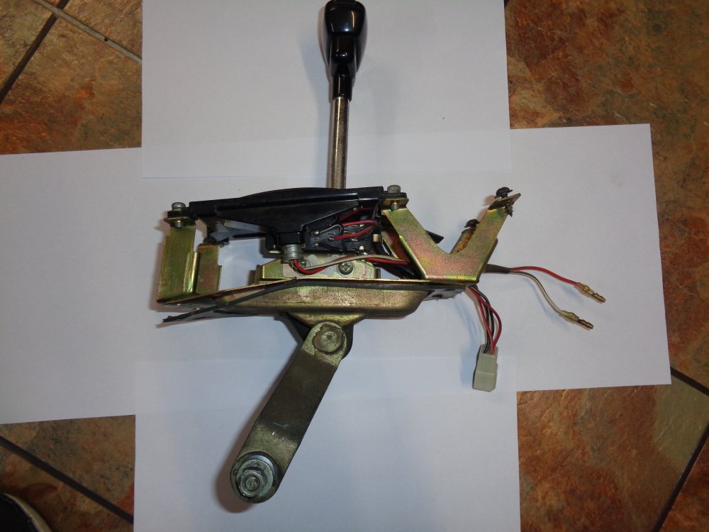
I went looking for an auto shifter I knew I had in the shed somewhere, that I removed from my KE30 when I did a manual changeover. Altezzaclub's wiring diagram is how all auto Corollas were wired, with maybe small variations, or maybe different coloured wires. I can't imagine that Toyota produced some autos with the neutral lock-out switch not incorporated into the auto shifter. Your photos don't show the area under the plastic ware, where the switch is located. You can clearly see the switch in the pictures below. This switch is a combination switch. It does two functions. 1. It has a N.O switch that only closes when the shifter is in neutral. This allows the starter relay to energise, only when in neutral. This is as per Altezzaclubs diagram above. 2. The second function of the combo switch is a N.O. switch which only closes when in reverse. This turns the reversing lights on. I just buzzed these out with the shifter I have here. So there are a total of 6 wires, coming out of the auto shifter. 4 off those are in a plug, and the other two are single wires. The plug contains the wires for the reversing & Neutral lockout switching. Plug: Red wire with White stripe & Red wire with Blue stripe are the reversing switch. Black Wire & Black Wire with White Stripe are the neutral lock-out switch. The two loose wires . . . . White wire with Black Stripe, & Red wire with Black Stripe are the illumination light, for the auto console, as Altezzaclub pointed out above. From the photo, you can see that the plug lead is only 9 - 10 cm long, so the matching socket must be close somewhere behind the console. I know that's where I found mine, and just added a shorting link between the Black & Black with White stripe socket terminals. P.S. From memory, when I drove a few of these olde auto Corollas, the position of the auto shifter in neutral was quite critical, and you had to jiggle it a bit sometimes to get it to allow the starter circuit to work. While holding the key in the hard clockwise start position, jiggle the auto shifter that is in neutral & see if that has any effect. Trust this assists Cheers Banjo


-
Thanks Mal ! Just beautiful. Be sure to put some pics up here, when it has all gone back together. Strangely, I was following a current model Corolla Hatch this morning, that had a colour that I haven't seen around, on a lot on Toyotas, that was reminiscent of those colours of yesterday. I looked it up on the web, & found it is not available on all models. In the Corolla range, it only appears to be available on the Hatch. It is called "Citrus". I have to spray my KE30 2 door shortly, & am torn between whether to stick with the original colour (my wife calls it "baby pooh"), or one of the newer colours, that are similar, but more up to date. There is even a Ford yellowy gold colour that looks very good, that would go over the original colour pretty well. However, I think I'm a bit like you, & would like to keep it olde skool look. I've sourced the original colour code, so getting the original colour matched is not an issue. Thanks for the picture of your RA65 Celica rally car. My wife & I had an RA40 years ago, and travelled far & wide interstate in it. It was a great travelling car; loved cruising, and you could always lay the back seat forward & sleep stretched out in the back. My wife always referred to it as "SillyCar". It was anything but, and was very reliable & had a lovely gearbox. Cheers Banjo


-
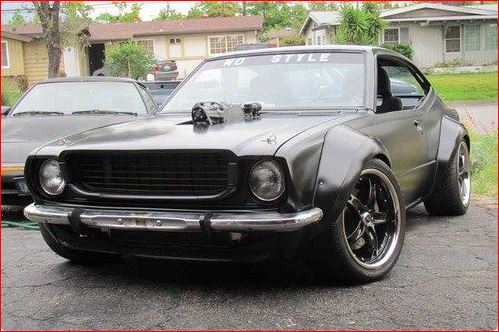
Hi Mal, Absolutely beautiful ! What a find. I started with an RA40 Celica, a KE35 Coupe years ago, then a KE55 Coupe, & now the "getting rarer" KE30 2 door sedan. However, my favourite would be a TE27; but if not, I'd settle for a Ke20 or KE25 like yours. They still have one of the best appearances of all the Rollas, to my mind, when they are lowered slightly, with widies & flares. The agressive grills, of which there were several types, also give them that "mean", but attractive extremely ageless look. Some of those USA equivalents, like the SRs are awesome. I think I'll drool over your photos today. So what have you got in mind for the "serious" upgrade, other than the respray ? Cheers Banjo
-
Hi Mal, I'm really sorry I didn't retain those clips. I will keep my eyes open for some more. I'm assuming all the KE Rollas used the same head lining bar clips. How many are you needing for the KE20 ? I think the KE55 Coupe, that I "dissembled" at the weekend, had four (4) on each side. I just went out in the yard, where I had been working, & found a broken one in the dirt. At worst, you could probably make some up out of steel. The steel rod bars are 5.1mm in dia. A piece of steel tube to suit could be cut into 20mm lengths, and then tack welded to a thick steel nail , 5mm in dia., cut into 18mm sections. Should work OK. Nice paint job ! Is that an original Toyota colour or something you just liked ? Very much in keeping with popular colours of that period your KE20 was manufactured. Keep the pictures coming, as you progress with putting it all back together. Love complete rebuilds ! They involve every aspect of the car. Cheers Banjo
-
Hi Omar, Welcome aboard ! In which country are you located ? I note your car is LH drive. The problem will be quite simple, as there is no power to the ignition coil & also no power to engage the starter. The problem will be either the ignition fuse, the ignition barrel itself, one of the electrical plugs & sockets at the base of the steering column, or possibly the transmission switch in the centre console, that only lets you start the car, when it is in neutral. A test lamp should be able to determine the issue quickly. I'm putting my money on the transmission switch. I would temporary run a wire from the battery positive, to the +ve terminal on the coil, and then touch a +ve voltage to the starter circuit as you have described, & see if the car starts. Off course, all other things like fuel in the carby, fuel in the tank, new oil in the sump, & water in the cooling system, must be right first. Take off the air filter & squirt some "Sure/Quick Start" pressure can stuff, down the carby throat before trying to start it. 22 years is a long time to sit idle, & lots of things will have become stiff & stuck. A better idea, would be to remove all spark plugs, squirt some engine oil down the cylinders, & turn the engine over with the starter a few times to loosen things up. At the same time, disconnect the fuel line into the carby, & check that fuel is being delivered whilst turning the engine over. This will prove the fuel pump is working & that there is fuel in the tank & lines. Also change the fuel filter prior to this, as the paper filter would have broken down & blocked. I actually started a 5K engine at the weekend, that had been sitting idle out-doors for 12 years. It took 30 minutes to do the above suggestions, & it started first kick. I couldn't believe it. If it starts, but runs very rough, or won't idle, I would suspect the carby. Either remove & thoroughly clean & reassemble, or maybe you could get away with just removing the top, & giving it a real good spray of a carby & throttle cleaner. Let us know how you go. You certainly have a lovely little Rolla there. How many klms/miles, does it show on the odometer/speedo ? Cheers Banjo
-
Hi Mal, Bugga ! I stripped my donor Rolla at the weekend, including removing the headlining & bars. If I'd known you were after the little plastic clips, I would have delicately removed them, as they are very brittle when 40 years old. Unfortunately I yanked the bars out & broke them all. Cheers Banjo
-
No Dave, a comment like that would be "over the top".
-
Hi Marius, Good one ! Do strange strange things happen in Norway ? Hah ! Hah ! Cheers Banjo
-
Anyone who is interested in learning about ignition advance in our K series engines, and its importance & possible implications, cannot read a better short write up than this one by Julian Edgar on the AutoSpeed website. It is so crammed full of general & specific information, obvious written out of experience, rather than theory. I've read the article several times, & gained more insight with each read. http://www.autospeed.com/cms/article.html?&title=Getting-the-Ignition-Timing-Right&A=109132 I just love the photo in the article showing an engine on a test bed/engine dyno, with the advance obviously very retarded, such that the combustion is taking place in the exhaust manifold/header, with it literally "glowing". One of the many indicators of a well tuned engine at maximum power output, according to this article, is the lowest exhaust temperature possible. Has inspired me to put a couple more temperature sensors on my air intake & exhaust system, & just see what is going on in my engine, under different environmental & driving conditions. Cheers Banjo

-
Hi Marius, If your speedo "odometer" is still showing the correct number of kilometers the car has travelled, but the speedo itself is showing an increased speed, then the issue is within the speedo itself. Usually not something you can do to resolve this, although very close inspection of the fine spring & magnet that allow the needle to turn, may disclose/indicate something. Best see if you can find another speedo. Cheers Banjo
-
-
Here is a good read, regarding your concerns about excess retarded ignition timing causing overheating. https://www.smokstak.com/forum/showthread.php?t=70385 There was someone on here recently that had the timing way out, and had combustion happening in the exhaust manifold, such that the whole manifold was glowing pink. Frightening sight if you lifted the bonnet at night. Cheers Banjo
-
Altezzaclub is quite correct in saying that your result is normal, with a static advance setting of 8 deg, but when you plug the vacuum hose back on, it rises to 20 deg dynamic advance. At 900 rpm idle the bob weights should be tucked up against their stops, held there by the springs, and having absolutely no effect at all. The 20 deg of "dynamic" advance you are seeing with the timing light is the sum of the static advance plus the 12 deg advance contributed by the vacuum actuator. You are never going to detonate at 20 deg advance when there is no load at idle, when the mixture is very lean. Don't forget that a lean mixture requires a lot more advanced spark, as it is harder to ignite, than a rich, dense combustion mixture. The vacuum advance existing in your inlet manifold has little or no relationship to the revs of the motor. It is purely a simple way of practically feeding back to the ignition system, what the load is on the engine is. You would not be surprised to know that when you have got your car into top gear, driving on a flat road at say 60-80 klms per hour, with no passengers, & no load of cement bags in the boot, you are probably only using/need about 30 -40% of the power your engine is capable of. Your foot is not flat to the floor, and the mixture is reasonably lean, and you need all the advance you can get to make the engine run as efficiently under those conditions. In years gone by it was popular to fit aftermarket vacuum gauges to your dash. (I had one) I think there were a couple of car brands that fitted a gauge in the dash, which they called an economiser. It didin't have units on it. It had a green & red zones at each end, and a zone in the middle called the economiser zone, where you tried to keep the needle whilst you drove. It stopped you from stamping on the accelerator, which usually shot the gauge to the end. The most important thing, about ignition advance is to ensure that the components in the engine that create advance & retard are working as intended. Remember our Rollas are around 40 years "olde" & getting tired. Things do wear out & break, and forgotten about, like those little bob weights that hide in the bowels of the distributor & rarely see the light of day, let alone get oiled. I've pulled some distributors out of Rollas, & after removing the contact plate been faced with weights rusted and pivots worn so badly they didn't have a hope in hell of ever performing as they were intended. When I've cleaned them up, oiled them & put it all back together, the owners have indicated it was like a whole new car. Vacuum advance units do fail, but are very easy to test. ( A piece of plastic tube & your mouth ) Hope that helps.


-
The effect on performance of the vacuum advance on your distributor, is quite different, when the vacuum pickup point is on the manifold (manifold advance) as opposed to connected to the carburetor point (call ported vacuum). When connected to the carby, the vacuum point is basically blocked off by the butterfly at idle. That is probably why your car "revs so freely". As Altezzaclub has mentioned above, the K series engines will accept a large amount of advance at standard compression ratios, without detonation & pinging. I've been running "manifold advance" vacuum into a transducer which produces a 0-5Vdc signal "mapped" to a programmable ignition, and I regularly obtain 45 deg of advance, without a sight nor sound of a ping. Never under estimate the difference even a small change in ignition timing can make to the overall performance of your normally aspirated K engine, as this video clearly demonstrates. All good fun. Cheers Banjo
-
We all talk about static timing as being 8 or 10 or 12 deg BTC, as being important, but really it is only an initial "static" setting, that allows us to get the car started. The most important ignition setting is the dynamic advance setting, which is the advance whilst the car is running, under various load conditions. However, few of us ever get to check the dynamic setting. We just assume it gets there. The maximum dynamic setting, is the sum/total of the static setting (rotating the distributor at rest until the points just open) plus the maximum centrifugal advance, which is the function of the little "bob weights" under the dizzy plate, that don't get looked at often. If you do ever pull your dizzy to bits one day, you will notice that the little bob weights, or the adjacent plate, have a little number stamped on them like 14 or 18 or 21 or something similar. This number is the maximum number of degrees of advance, those particular centrifrugal bob weights & springs can provide, Some people play with these weights, end stops & springs, to increase the maximum advance possible. You will also notice that the two little springs are different, one being "lighter" than the other. This is so one bob weigh moves out first, The other heavier one then adds to it, as revs increase, to provide a 2 stage advance curve. So lets say your static advance ignition setting is 12 deg., & lets say the bob weight/s have 14 stamped on it. The total advance possible is therefore 26 deg. The maximum advance in our little K series engines is all achieved by the time the revs have reached say 2500 - 3000 rpm. So the most important thing to determine, to my mind, is to ensure that when your engine is running at 3000+ rpm, that the advance reaches this possible maximum. So what about this vacuum advance you/we are discussing here. As vacuum decreases, with the engine under load, with W.O.T. (wide open throttle) the vacuum actuator on your dizzy, actually retards the advance. This is because under load, the engine "sucks" harder, and with greater density, it ignites easier,earlier, (not as lean), so not as much advance is needed. That's it in a nutshell, but there are plenty of places on the net where you can read about that in more detail. So this is why when you set your static advance setting, you always take off the vacuum line & block it, so it has no effect, on the setting. So once you get your motor running, you should set the dynamic advance to the maximum recommended possible. As we can't change the bob weights action, without modifying them, the maximum achievable is still adjusted by rotating the dizzy, with the clamp just nipped slightly. However this is done at 3000+ rpm, rather than at idling. The reason this method is not used widely, is that you need a timing light to check that you are achieving say 26 deg, as in the example above. However, a timing light is a very good addition to your toolbox, if you are serious about getting the most out of your K series motor. The problem with this technique is that to read 26 deg of advance on the timing chain cover is difficult, as the markings usually only go to 20 deg BTDC. Now you can guess where say 26 deg is, or pre-mark it on the case, or get a adhesive degree strip, to stick on the edge of your crankshaft pully, but it must be a strip designed for that precise dia. pulley. The timing light manufacturers have overcome this issue, by adding a knob you can turn to retard the flash, until it lines up with TDC instead of say 26 deg. The 26 deg, is then read out on a little LED screen. From your description, it sounds like the current p/u point on the inlet manifold is causing your problems, or maybe the vacuum actuator on the dizzy is faulty. Try the sucking on a plastic tube connected to the vacuum actuator, & see if the dizzy contacts plate moves. You might also have an air leak on the inlet system somewhere that is causing the engine to idle fast. The first bob weight usually starts to move around 1200 - 1500 rpm. The idle must be down around 800-1000 rpm, to ensure that the bob weights are not advancing the timing at idle. The possibility is that a bob weight spring has fallen off and there is nothing holding back one or both of the bob weights. Let us know what you find. Sounds like your teacher is doing well, and created a great interest in you to question why things work as they do. Cheers Banjo
-
Wow ! If they were any cheaper, they'd be giving them away. Thanks for the feedback. I know a little KE20 around here locally, belonging to a Rollaclub member, with rather dim headlights, that could well benefit from one of these. I'll put her in the know. Cheers Banjo
-
They look like a good alternative solution, except they are designed for plugging directly onto an H4 headlight bulb, rather than an external driving light. I guess Rob could always cut off the H4 plugs on the harness/cable, & directly connect to the trailer plug he was considering using, so that the driving lights, pod could be moved, to open the bonnet. Has anyone used these ebay harnesses ? Would be nice to hear from someone, as to their quality. They certainly are cheap ! Cheers Banjo

-
Hi Rob, I think the relay you are referring to is the NARVA P/N 72386. It has five (5) connectors, but is not a "changeover" relay, like many others. There are 2 off output N.O. terminals called 87, that are the same point, so presumably two (2) loads can be easily connected to the one relay. These are a high quality European relay, and I would think, not cheap. You could probably purchase a pack of five (5) "China" 12V Auto Relays for less that 1 off NARVA relay. Here is a circuit you could use to wire up 4 off Driving Lights using 2 off NARVA relays. I would suggest 2 off fuses, so a light failure causing a blown fuse does not take out all the lights. I would also suggest that you wire them straight back to the battery +ve terminal, which you advised is not too far distant. A 60A Maxi in-line fuse connected to the terminal, will portect the wiring between battery & relays/fuses. This will minimise voltage drops between battery & lights. If you choose to go the cheaper "China" auto relays, I would suggest using the ones with the built-in 30A blade fuse. For less than $ 20.00, you can get 5 off relays, with fuses & leads/tails, delivered free. These relays mean you don't have to worry about installing an inline or mounted fuse block. Let us know how it all pans out. Cheers Banjo


-
Hi Rob, Sorry missed your post over the weekend, as I was away. Quick question ! The four (4) off driving lights in the pod. Are they all identical ? Are they LED, or conventional ones ? What is the DC current draw on each of them, with a 12-14 volt supply ? How close is the battery to the front of the car, or where the lights are to be located ? Eliminating possible voltage drop is always the most important element in this particular exercise. I've done a couple off these previously, for rallying applications, and have found that multiple relays are best, where there are multiple driving or fog lights. The reason being, is that when rallying, you definitely do not want your driving lights droping out, as you crest a hill at 100 klm/hr, in a dark forest. There are a lot of the standard 30A automotive relay around that originate from China, that are not of the highest quantity. I use them myself, but do take precautions. Primarily, many of them are not sealed & water ingress at the front of the car, from splashes on water crossings during rallying, could be an issue. The direction of mounting the relay, can assist, and you can seal them with a bit of Sealastic or similar. Just never mount them with the spade terminals facing up, or towards the front of the car, behind the grill ! Shock proof mounting them, also relieves the chance of a rough road resulting in a relay dropping out temporarily. If you have one relay per light, (or per 2 lights), then if a relay fails, whilst driving, you won't be in the dark. Likewise, I like to fuse them separately for the same reason, so if one light, or it's lead causes a s/c, it doesn't take out all four lights. Cheers Banjo
-
As you only did the solid lifter conversion about 4-5 months ago, & used part of the original hydraulic lifters, can you describe what that conversion entailed ? Now you mentioned that the tappet clearance is getting out of wack by itself, that is possibly indicating that there is something not right with the lifter mods. Cheers Banjo
-
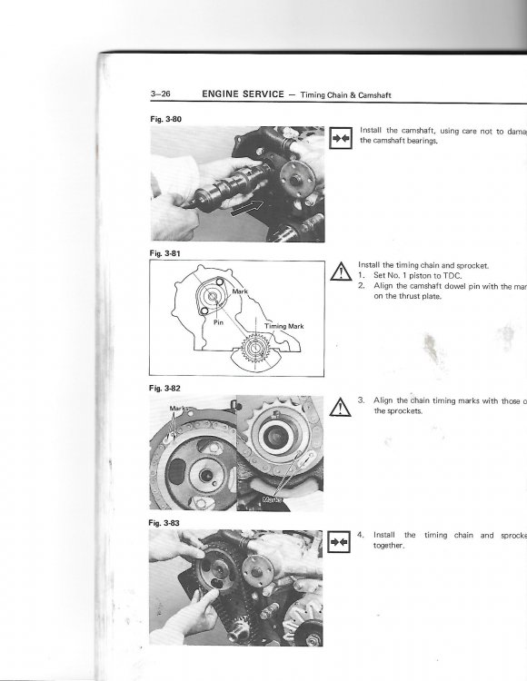
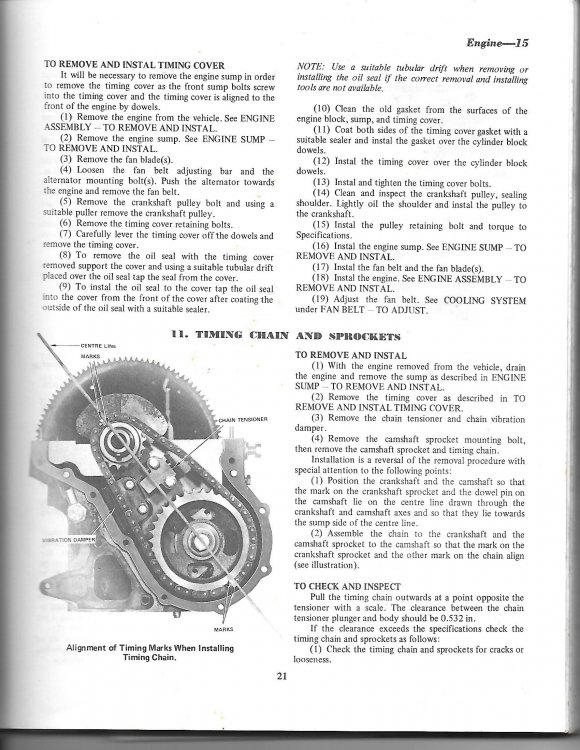
Hi Ben, Dave's suggestion is excellent, as having the genuine Toyota "Yellow Bible" on the K Series, is probably one of the best investments you'll ever make, if you are going to play with a K series engine. I got one early in my journey, which covers 2K to 5K-C, and it has been invaluable. Most functions of reassembling a K Series engine are straight forward, simple, & logical, but fitting the timing chain, & aligning the crankshaft & camshaft sprockets, is one area, where if you get it wrong, it can prove dissasterous, & cause a lot of frustration, after the engine is assembled & ready to test for the first time. By that time the engine is probably already back in the engine bay, & all hooked up. The alignment is critical, & is covered in the "Yellow Bible" & the Haynes/Gregorys manuals. Essentially the timing is carried out with the engine at TDC on no: 1 & 4 cylinder. The crankshaft sprocket should be fitted first to the crankshaft, with its key fitted. The crankshaft should then be turned slightly, if required, until the "dot" marking on the outer of the crankshaft sprocket is on the lower side of the engine, and is in line with an imaginary line passing through the centre point of both crankshaft & camshaft. (see diagram in pictures below) The camshaft is then rotated, without its sprocket until the locating pin for the sprocket, lines up with inner mark on camshaft retaining plate, which again, are all in line with the imaginary line, passing through the centre points of both camshaft & crankshaft. This is now the critical point. The camshaft & crankshaft cannot be allowed to move, whilst fitting the chain. With both sprockets on a flat surface, off the engine, fit the chain to both sprockets, such that when you pick up both sprockets & chain, that they slide onto the keyway (crankshaft) & locating pin (camshaft) without rotationally moving either sprocket. When fitted, a straight edge, (like a steel ruler) should line up with both outer sprocket marks & the centre points of both crankshaft & camshaft. Actually much simpler than it sounds, when you describe it, but it is important, because if the chain is out one or two links, then the engines valve & distributor timing will be out dramatically. Have a look at the relevant scans from the manuals below, & it should all gell, as "a picture paints a thousand words". P.S. The manuals refer to markings on the chain, which I've never been able to find, because the chains are old & discoloured. Whilst laying the sprockets on a flat surface, with a straight though the centre point of both sprockets, & sprocket markings, I've just put a dab on "white Out" on the relevant link at each end to assist. Good luck, & let us know how you go. Cheers Banjo
-
I didn't know Toyota made engines for M4 Sherman tanks ! Just goes to show, you're never too olde to learn something every day ! I guess it is like an oversized 7K ? Cheers Banjo
-
Hi Max, Any update on what you discovered with your 4K engine with glowing exhaust manifold ? Cheers Banjo
-
Hi Graeme, The dizzy aluminium body should have a little plate on it down on the side, with all the details, including which K series engine it made to be fitted to. The Bosch dizzies are usually larger in dia. than the Denso ones. Toyota used both brands at different times. Do you know whether this dizzy is the original one fitted to this particular engine. I presume it has points. Post a picture of it, if you can. Cheers Banjo


