

Banjo
-
Posts
2028 -
Joined
-
Last visited
-
Days Won
98
Content Type
Profiles
Forums
Events
Gallery
Blogs
Everything posted by Banjo
-
Hi Peter, To prove the issue is a defunct fuel pump, simply remove it, put a piece of tube on the inlet; put it in a can of petrol, & work the lever by hand, & see if anything comes out. If it doesn't, then you've solved your problem. If it does work, then look for a blocked fuel filter, or a blocked fuel line from the tank. I think you are nearly there ! To check the fuel line, remove petrol cap, and get someone to listen at the tank filler, while you blowing back down the line. Do not use compressed air. If there are any rubber sections in the fuel line, then these can break down inside & block completely, even if the line looks OK on the outside. Good luck ! Cheers Banjo.
-
Hi Peter, In your response you said . . . . How did you determine the spark plugs were igniting ? Was it trying to start ? (Spasmotic combustion) Or did you remove spark plugs and just connect them to the leads, with the spark plug base grounded ? Cheers Banjo
-
Hi Peter, Unfortunately, it may have been the distributor, but if you changed it over, & didn't get the replacement one inserted correctly, with timing right, it will still not start. Are you sure the timing of the replacement dizzy is correct ? Turn the engine over slowly by hand with a 19mm spanner or socket on the crankshaft pulley, until the timing "nich" on the cranshaft pulley lines up with the 0 deg timing mark on the timing chain case. Then carefully remove the dizzy cap & see if the rotor is pointing towards the cap point where either No 1, or No 4 spark plug lead is connected. If the rotor does not line up with either, then the dizzy has been fitted incorrectly, & therefore should be taken out, & reinserted. There are plenty of instructions on this website, how to fit & time a dizzy properly. If it does line up, it could still be out 180 deg on the dizzy. You can correct this temporarily, by moving all the leads around the dizzy cap 180 deg. I'm presuming you have measured +12V at the positive terminal of the coil with the ignition turned on. If not, it could be an open circuit coil ballast resistor. I would also suggest removing all spark plugs & inspecting them. Whilst out, undo the union of the incoming fuel line into the carby, & turn the engine over with the starter motor. If fuel comes out around the loose union, then there is fuel available & the pump is working. While the dizzy cap is off, ensure the points are opening, when turned over by hand. Try those suggestions & if it still doesn't work, then let us know the results of my suggestions, & we'll see if we can't narrow it down at least to either fuel or ignition. Cheers Banjo.
-
Hi Lochi, Don't know how I missed your post & this thread. I love a "who done it" scenario, requiring a little collective detective work. Did you remove the head to discover this, or just peer down the spark plug holes with a light ? I'm very skeptical that a running engine, could just get to a point in time, where the engine suddenly arrived at a locked condition every 360 deg, as a result of carbon build up alone. Hmmm ? Love to hear some more details on how you found that, & if you have permanently solved the issue, & it is running again. Cheers Banjo
-
Most dashes look olde & tired at night, with those little 5W filament bulbs getting olde & dim. I quick fix, is to buy a few of the T10 LED bulbs on line. They are now quite cheap. http://www.ebay.com....Qhzotr_c_tmU8Bw I grabbed a few, stuck three (3) off them in the 3 x "back light" holes, & the effect was immediate and brilliant. The blue LED light even makes the "orange" needles on the meters look new & fluroesent. If the bulb does not work when you first plug it in, then remove, rotate 180 degrees, & reinsert. The LEDs are polarised, unlike the filament bulbs, & will only work with the right orientation. There is a 50/50 chance you'll get it right the first time. The LEDs will not allow you to use your dash light dimmer, but you won't need or want to, once you've got these cool blue LEDs. Almost makes my 42 year olde Rolla look modern at night. i wondered why the clock back light did glow blue, until I remembered it is an independent unit that fits into the dash, & has it's own torch type filament bulb. A few months ago, I needed a cheap tacho to do some ignition testing on the bench. I purchased one on ebay for < $ 20.00. http://www.ebay.com....MQAAOSwTA9X62qZ At the weekend, I had the dash out, fixing the guages' voltage regulator. I noticed the clock assembly is only held in place by 3 screws, & looked to be about the same diameter as the 52mm tacho I had on the bench. A few minutes later I had the clock out, & couldn't believe the 52mm tacho slid perfectly into the hole left by the clock. It even jammed itself with the little plastic ribs on the meter face surround. When I hooked up the two tacho back light wires to the dash, I was pleased to find it had a blue LED in it. The whole dash now looks totally co-ordinated. If you are going to buy one off ebay, get one with a black face & white lettering to match the speedo meter face. They come with simple instructions. Just 2 wires for the back light. 2 wires for 12V ignition "RUN" & one green wire to the trigger dizzy or ECU, if you've got electronic ignition. So there is a way, for < $30, you can really spruce up your dash. Cheers Banjo
-
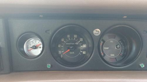
Got up on Saturday morning & started my KE30 Rolla, but no fuel or temperature gauge movement. Everything else worked fine, & no blown fuses. As the fuel tank & level sender is at one end of the car, & the temperature sensor is on the engine, it was a fair bet it was not a wiring issue. Then I remembered it will be that little voltage regulator, that sits on the rear of the dash assembly, & powers the fuel & temperature gauges. These two gauges run at 7 – 8 volts instead of 12Vdc, so that the two gauges read accurately, whether the battery is fully charged, or very low. So out with the dash assembly, to have a look at the regulator. Now I had one go bad years ago, & I knew where it was located, but on my dash rear, there was no regulator. There was a little bit of blue plastic sticking through the PCB, where it should be mounted, but not on mine. The PCB had 12V IGN & 7V marked on it, with the posts & nuts for locating the meters, but no regulator. I hooked up 12V to the dash, & measured a big fat 0Vdc on the 7V posts to the meters. So I knew what the problem was, but where was the regulator. I looked in the garage & found two other dash assemblies, both out of KE55s, & both had regulators visible on the back of the dash PCB. I noticed the fuel gauge had three posts; 12V IGN - 7V - Chassis/Ground, whereas the temp gauge only had two. I took the PCB off the plastic dash frame & removed the fuel gauge. Careful study of the fuel gauge working, indicated that the 7Vdc regulator, is built into the gauge, which then supplies 7Vdc to the temperature gauge. However the regulator is not an electronic one like the KE55s, but a rather simple electro-thermic pair of contacts that maintain an “average” 7Vdc to power the meters. This works because both gauges are electro-thermic, & have very slow response times. This contact is constantly opening & closing at varying on/off ratios, dependent on what the battery voltage is. The lower the battery voltage is, the longer the points will remain closed. So even if it was working perfectly, you will not get a steady voltage when you check the 7Vdc point, with your multimeter. You get 12V or 0V, but never exactly 7 volts. My fuel gauge regulator had pitted & worn contacts, & I could have delicately cleaned them, & possibly got it working again. However, after seeing how basic & crude the regulator was, I decided to insert an electronic LM317 DC regulator. This regulator will handle DC voltages up to 37V, & can be set to output basically any voltage between 2V to 35V, using just two (2) resistors. Altronics sell a little Silicon Chip kit using this regulator, called a model K3220. You can buy then on line for about < $ 10.00 + P&P. However, my fuel gauge had never read quite full, when the tank was topped up. I now had the chance to fix that, so that the gauge would read full properly. I filled my tank up at $ 114.9/ltr, & I put my variable power supply across the 7Vdc terminals. The fuel gauge indicated about 90% full. I wound the power supply up to 8.0Vdc & the gauge read almost 100%. I thought, if I make one of the resistors variable in the K3220 kit, I could then adjust the DC gauge supply to make the fuel gauge read exactly 100%. I used a 500 ohm multiturn trim pot, & to cut a long story short, the gauges work just like they did when the car was new; maybe even better. The little regulator can be mounted anywhere behind the dash, with only three (3) wires to be connected. If you fit Utilux post lugs to these wires, you don’t have to even solder it to the PCB. 12Vdc input to the regulator goes under the post nut for 12V on the fuel gauge. 7-8Vdc lug goes under the 7V post on the fuel gauge, & GND goes under any of the outside edge screws holding the PCB to the blue plastic frame, that pass through the ground plane on the PCB. However, you must disable the electrothermic regulator inside the fuel gauge. Don’t butcher it, as it may effect the operation of the gauge itself. I simple placed a strip of thin cardboard (manila folder) between the contacts, and stuck it with some double sided tape so that it would never fall out. Probably the hardest part of this little exercise is getting those two round multipin plugs on the wiring harness to plug back onto the back of the dash assembly. If anyone wants the resistor values for the regulator to produce a 7-9Vdc adjustable output, just give me a yell. Cheers Banjo
-
Jeremy, if you Google "Offset Crankshaft Advantages", you will find a lot of discussion for and against this technique, in various sites. I have also heard of off-setting the piston pin in the actual piston, which may have similar results or advantages. Cheers Banjo
-
My concern was that the sleeves / liners in the 2NZ-FE are not a wet sleeve, or replaceable. The sleeve apparently has a rough outside finish, so it "bonds/locks" into the alloy bock casting very well. Apparently it is so thin, it can't be rebored. Apparently it is very efficient at getting heat out of the cylinders, & into the block & water jackets. However, the more people I talk to, the less I am concerned about longevity, as everyone says they are just like the K series; unbreakable & go forever ! P.S. Apparently, the offset of the crankshaft C/L in relation to the C/L of the cylinders, greatly reduces the wear factor on the cylinder walls. Here's a good read about the 2NZ-FE http://toyota-club.n..._faq_nz_eng.htm Cheers Banjo
-
Hi Jeremy, You are right that if the clutch cable adjustment is not right, so that there is a gap between the throw out bearing face & the fingers of the pressure plate, you will get the throw out bearing spinning all the time, & not just when you push the clutch in. You will however have prior warning to this condition, as the throw out bearing makes a "wheeeerring" sound as it dries out, long before the throw out bearing collapses with resulting crunching noises. Cheers Banjo
-
I discovered this little comment whilst researching on the Yarisworld.com website . . . . So the 4AGE started life as an east west engine, & has been widely used in Rollas with in a north/south configuration. If this rumour turns out to be fact, then any good in-line 5 speed gearbox that bolts up to the 4AGE series with a bell housing adaptor, would also possibly suit a 2NZ-FE engine. Can anyone see anything wrong with this logic ? If not, then what gearboxes would meet that criteria ? Cheers Banjo
-
I did just find something out about the 1NZ-FE & 2NZ-FE engines, that does bother me a little. Being an aluminium block, they have a relatively thin cylinder wall liner/sleeve, that does NOT allow for reboring. Sounds to me like once the bore is too worn, its a throwaway block, unless some smart engine builder somewhere, has worked out a way to fit a new sleeve to the worn out block. However, these engines are known for their longevity. The inspection certifier who checked this Echo before I bought it, said they regularly get to 250K klms, and he has seen a growing number with 350k klms on them & still going strong & not blowing smoke. Cheers Banjo
-
Nope ! Its a photo I took some time ago. Cheers Banjo
-
Hi Jeremy, Got some news for you, & I'm afraid it is all bad. It aint the throw out bearing, because its not even turning when you are driving & in gear ! Hope you've got another spare gearbox hanging around. Cheers Banjo
-
Love your new Avatar Jeremy !
-
Thanks James for that Toymods link. I read through it. It was posted nearly 10 years ago, when the 2NZ-FEs were relatively new, & the prices for second hand ones were fairly high. Interesting reading. I note that the thread stops, with it appearing that the swap never went ahead. Keith, the head has a water outlet on the back of the head going back to the radiator header tank, but I don't think it will be an issue, as I do not think the engine will have to go hard up against the firewall. Easier to rearrange than a distributor on the 4AGE. The throttle body might have to be repositioned, as it sticks out beyond the rear of the engine. Someone jokingly remarked in the Toymods link, that you could cut a hole in the firewall, & but the air filter box in the glovebox. There are three engine / gearbox mounts on the Echo setup. One right at the front of the engine. One down onto the cross member next to the exhaust header. One apparently under the battery, off the gearbox housing. Next time I put it up on the ramps, I'll pull off all those plastic stone guards around the engine, so I can have a good look. Maybe the adaptor plate for the bell housing/gearbox could be profiled to hang out each side a little, so rubber engine mounts can be attached. The real question is what 5 speed gearbox would you mate with it. As you point out, the T50 are getting olde & hard to find, & the K50 boxes have issues of bearings not being available now, if they are to be refurbished. I know the MX-5 sounds simple & straight forward, & a lot of guys like to fit the Nissan motors to their Rollas. I like to keep all my mods Toyota. I must admit though that I do have a Pajero master cylinder fitted, to feed the larger Cressida brake calipers & rotors fitted to my RA65 Celica struts on the front of my KE30 ! I'll do a bit more research on this, & see what I come up with. One nice thing I liked about the 2NZ-FE in the Echo setup, is the fact that it still uses an accelerator cable, instead of electric throttle like in later Toyota Corollas etc. Makes it very easy to integrate with the KE existing accelerator pedal & cable. Cheers Banjo


-
Now Now ! That's not a nice way to treat a Rolla. As Donald would say. That could be fake news. Maybe you just rotated the photo, & got your friend to stand on his head. Ha Ha !

-
Hi Jeremy, I listened to your utube video & I can hear what you are talking about, the second time you rev the engine up. Could well be a sticking valve. You could try to unstick it, by using one of those additives you put in your fuel, or it maybe it's time for the head to come off. The blanking plate for the mechanical fuel pump hole in the block is not hard. I just used an old flange off a mechanical fuel pump, to mark an outline on a piece of steel. Then cut & filed it, until it looks good, drill two holes & you are there. Just use a fuel pump gasket to seal the joint to the block, or use the plate shape you have cut & filed, as a template on a piece of gasket paper. Cheers Banjo

-
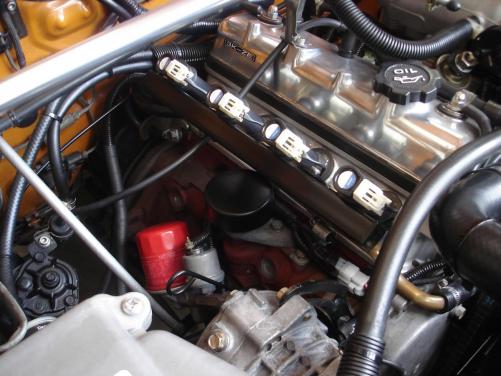
Hi Guys & Gals ! Sorry this is not going to be short, but it’s just a bit of lateral thinking at present, & I’m throwing it out there. Back in early January, I posted on here that I was looking for a Toyota Echo for my “petite” 18 y.o. daughter, who needs a first car, with a seat which has enough adjustment, so that she can reach the pedals. I found a good one here in Brisbane about 10 days ago, with which I was very happy with. Like all good dads, I spent the previous Saturday & Sunday, plus a few hours yesterday, going over the car completely, doing a full 160K klm service. Every fluid, every filter, spark plugs, wiper blades, every adjustment; basically a very full service. I half expected it was going to be a bit difficult, as I assumed the east west 2NZ-FE engine would be crammed into the small front engine bay. I was pleasantly surprised how easy it was to work on, and after a full day on it, had fallen in love with the 2NZ-FE engine. These engines, have a very good reputation for being strong, reliable, nippy, & very fuel efficient, from what I had read on the net. The spark plugs I took out, needed replacing, as the gaps were wide with the inner tips worn out, but the insulators were perfect, showing a lovely clean whitish colour. The more I worked on the engine, the more I loved it. Even taking off the throttle body & cleaning it with carby & throttle cleaner was easy. About the only unpleasant job, was removing the fuel pump/guage/filter assembly out of the tank under the floor, under the back seat. What a nightmare, to dissemble & fit the main & pick up filters. Everything else was pretty easy to get at. It wasn’t till later that night, as I lay in bed, I thought, “would it be nice if I could pop a 2NZ-FE in my KE30 2 door Rolla”. The next morning I roughly measured it up, & had a good look at its specs on the net. It certainly would physically fit in the engine bay fairly easily. Despite the 2NZ-FE’s sophisticated design, compared to a 4K donk, with cross flow head, 4 valves per cylinder, variable valve timing, electric cooling fan, fuel injection, & obviously computer engine management, the two engines are pretty similar. Both 1300cc, 75mm x 73mm, being almost “square”. However, the big difference is in output & fuel efficiency. A basic stock stand 4K will produce about 60 HP, whereas the 2NZ-FE puts out 84 HP, a 40% improvement. The 1500cc version of this motor is the 1NZ-FE, which appears to be the same block, but stroked to 75mm x 84mm, has an output of 109 HP. That’s a whopping 84% over the little 4K. The 1NZ-FEs were fitted to the Sportivo versions of the Echo & Yaris. My research indicates that there is a bolt on turbo kit for the 1NZ-FE which brings it well over 120 HP. By now, my head is running all sorts of scenarios. A quick look on the net indicates “long” 2NZ-FEs engines can be picked up for between $ 300 & $ 500. So I go looking on the net to see if anyone globally has swapped a 1NZ-FE or 2NZ-FE into a KE series Rolla, & I can’t find anything. I found one guy who made up his own adaptor plate, so he could fit a conventional in-line gearbox to it, but he didn’t say what car it was being fitted to. So if it is true that few, if any, have swapped them to KE Rollas; why ? My gut feeling it is probably because of lack of facilities on the side of the block to fit engine mounts. The existing engine mounts on the 2NZ-FE in my daughter’s Echo are high up on what would be the front of the engine, if mounted in a KE Rolla. The other one appears to be high up to one side off the bell housing/gearbox. So I get on the net this morning looking at pictures of this motor for sale at wreckers, zooming in on the photos of these motors, sitting on pallets, trying to see the sides of the aluminium block. Unfortunately, being a cross flow head the intake & exhaust manifolds cover these areas, & I will probably have to head off down to the wreckers to see one in the flesh for myself. I’d like to keep my 43 y.o. olde daily drive Rolla for another 10 years, & see it reach 50, but am thinking, wouldn't it be nice to drive a sleeper, with a 1 or 2 NZ-FE engine under the hood. We spend so much time & money, trying to tweek every last HP out of our K series engines, when now there are available second hand for $ 500, a standard comparable engine with everything we are trying to achieve with our K series donks. So has anyone heard of this being done before ? Has anyone contemplated it, & given it away, because of technical obstacles (like mountings) etc ? Would love to have anyone’s thoughts on this. As I said, it is just “lateral thinking” at this point, and maybe a pipe dream, but if it is “doable” then I’d be only too happy to grab an engine and give it a go. P.S. Would make a great Mighty Car Mods video. If you’ve ever watched the swap of a Subaru engine into a VW Bettle, you’ll know what I mean. Cheers Banjo
-
Hi Jeremy, I'm assuming that you have removed the mechanical fuel pump, & have blanked off the hole in the block. If you have fitted an electric pump, then it is advisable to fit it at the rear of the vehicle, close to the fuel tank, so that the suction distance to the tank is short, & the long run up to the engine & carby is under pressure, rather than vacuum. Just make sure that you current fuel line does have any leaks on the suction side back to the tank, where it could be sucking in air. Also make sure that your fuel tank is venting properly, in case it is building up a vacuum, working against your electric fuel pump. A good indication of tank venting issues, is to note whether there is any inrush air noise when you remove the fuel tank lid, when filling up with a low tank level. Some of the early Rollas just vented the tank into the chassis rail. Later models vented back into the air filter, via a line with a little in-line 1 way valve just near the steering box. It is a plastic valve which is easy to remove & test carefully with your mouth. HV arching inside the dizzy is still visible in total darkness, dispite the dizzy cap being opaque. However, arching inside the cap, is usually clearly visible by removing the cap & carefully inspecting. If they have arched inside the cap for some time, then the only fix is to replace the cap. You can clean them up, but they also seem to track again. Also make sure one or two of your spark plugs don't have very large gaps. This will cause breakdown, when the engine is under load, & the HV takes the shortest path to ground or chassis. Hope that assists, & let us know how you go. Cheers Banjo
-
Hi Jeremy, Almost certain your issue is ignition break-down somewhere. Repeat the exercise you describe, but do it in the dark at night. If there is a HV break-down in leads,spark plugs, or dizzy cap, you will see it clearly. Let us know how you go. Cheers Banjo
-
"Your braver than me. Messin with the missus's stuff.......... :rant:" Yeah, big risk, but my wife once had a Rolla. Her daily drive is a 2009 Rolla, but she still loves to drive my KE30 at weekends, going to the shops & places. Even washes it ocassionaly. Wire coat hangers ! Got dozens of them in the garage, with overspray on them, & always a couple in the boot, along with a roll of gaffy tape. Only tool kit you ever need with a Rolla. Cheers Banjo :thumbsup:
-
Sounds like there is a few coffee lids missing in a few pantries. My better half gets peeved off when I raid her pantry or kitchen when I need something in a hurry. I needed a piece of flat thin aluminium one day, & one of her baking trays was just the right size. A couple of weeks ago a hole appeared in the aluminium cutting deck of my Greenfield ride-on lawn mover. I needed something thick that was easy to cut, that I could shape & bolt on quickly, as I was half way through mowing an acre. Her plastic bread board, filled the bill perfectly. Luckily, she was out shopping at the time, but I did replace it the next day with a new one. Cheers Banjo
-
Hi John, A few guys on here have done what you are suggesting. Pretty relevant if you are going waste spark or COP (coil over plug), where you don't need a distributor at all. Brodie in S.A. did a very neat job on his Rolla when he went COP. I went waste spark, and just cut the dizzy down with a hacksaw & cleaned it up with a file. No machining needed. Waste Spark Commode Coils X 2 mounted on the block so little HV cable movement. I also blanked off the mechanical fuel pump, as it is now going EFI. It doesn't show in my pic, but I think I found a coffee jar lid that fitted perfectly over the "cut down" dizzy. Off memory, I think Brodie did a similar thing with a lid from a biscuit tin or something. However, the idea of a welch plug with a bit of machining, is probably the best solution, if you want something that is perfectly sealed, and oil drip free. Cheers Banjo


-
Interesting thread ! Bear in mind that the King Spring replacement front coils, are a bit stiffer than the original KE70 Toyota coils. This is because the King Springs are made with a harder material, & a vernier indicates the King Spring coil rod/bar is approx. 1mm greater in diameter, than the original Toyota ones. I did a front end strut & brake conversion on my KE30, using Celica RA65 struts with KE70 perches & coils, so i could get the struts right back into the strut tower, so the camber adjusters could provide the slight negative camber I wanted. The result was excellent, but the ride is a little harsh, as a result of the changed spring rate. I like it slightly harder, but there maybe others, whose "better half", would like the softer ride. In the past month, I completely re-shoed my Camry wide body, all round, with new struts, shocks & King Springs. The result was exactly the same. A harder slightly harsher ride. Cheers Banjo
-
Never did get a chance to get the head off this car & CC it, as the Rollaclub member young lady who owns this "moded" 4K in a KE20, uses the car as a daily drive to work, and can't really afford to have it off the road. She has advised that she has recently had a weber & electronic dizzy fitted. She is bringing it around soon, so I'll get to see what the result was. Sometimes, a too high compression ratio, can work against you, and you don't get the result you expect. I expect that is what happened in this case. Cheers Banjo


