Banjo
Regular Member
-
Joined
-
Last visited
Everything posted by Banjo
-
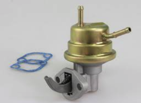
I'm assuming this is new mechanical fuel pump, fitted to a K Series engine ? The first thing to check is what volume the pump is delivering. Remove all spark plugs. Disconnect metal fuel line at the carby. Run a hose from this fuel line into a container, & turn the engine over for 10-15 seconds. Measure how much fuel is collected. You may have disturbed something, during the changeover. The smallest crack on the suction side of the pump, in a rubber hose, can cause horrible delivery issues. Did you refit the stand-off "gasket shaped" mounting block, between pump & engine ? Let us know how you go. Cheers Banjo
-
Love it Mate ! Great pictures ! I nearly split my cornflakes out whist reading that caption ! I'm a bit worried about those ramps you used to get the Hi-Ace on the back ? Lovely selection of cars there. My late brother had Hillman like that ! Good heavens ! Chrysler, Hillman, MG, BMW, Rolla, Foulcan, Volvo, Merc, Landy, I can't see two vehicles from the same stable. Does your club have a rule, one of each, or something ? I'd give you more than one (1) if this website allowed it. Cheers Banjo

-
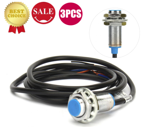
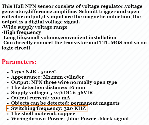
You are so right. kHz is slow, relatively. The microprocessor handling all the counting & switching is running at 32MHz. The only limit is the sensors themselves. That's why I use Hall Effect sensors, as they have the ability to switch very quickly, & produce nice clean square wave pulses. Here are the ones I am using for trigger & synch pulses, off ebay. They are built into a threaded tube, so are very easy to install & adjust the distance between the "blue" tip & the rare earth magnet. Believe it or not, these are about $ 4.00 ea. delivered, stocked in Australia. Better still are the specs. It can switch at 320 kHz, which means it could handle the 106 flywheel teeth counting application up to 18,000 rpm ! All good ! Cheers Banjo
-
Distributor Rotor Arc Just doing some calculations on where to allow the ECU output to switch on each COP, with their own inbuilt ignitor. My 5K flywheel has 106 teeth on the flywheel, so there are effectively 212 teeth being counted over 2 revolutions, which is a full 4 stroke cycle. As 212 teeth span a rotational angle of 720 degrees (2 revolutions) the distance between teeth of each count is 720 / 212 = 3.396 degrees. So the synch pulse is generated, & that starts an 8 bit counter (can only count up to 255), to start counting from zero, and at count number, say 22, Cylinder no: 1 is at TDC. The second cylinder to be at TDC will be no: 3, which 180 degrees further on in rotation. The 8 bit count at that time will read 75, ([180/3.396] + 22). Cylinder no: 4, will be the next one at TDC, which again is 180 degrees further on in rotation. The 8 bit count at that time will read 128, ([180/3.396] + 75). The last cylinder to be at TDC will be no: 2, which again is 180 degrees further on in rotation. The 8 bit count at that time will read 181, ([180/3.396] + 128). At a count of 212, a full cycle is completed, & the counter can be reset, & it will then await the sync pulse again, to repeat the full cycle count gain. So I want an "arc" or period of rotation, where a cylinder can be fired, anywhere between TDC & back to a point lets say 40 degrees BTDC. Most K Series distributors, limit the advance to about 35 degrees. So lets be generous and allow a cylinder to fire anywhere between say 50 degrees BTDC & say 10 degrees ATDC. That is an arc or period, of 60 degrees of rotation, during which the spark plug can be fired. This got me thinking, as the arc on the end of the rotor in the distributor is made that way, for the same reason, so the tiny gap between the end of the rotor contact & the post in the distributor cap are always opposite each other, throughout the entire advance period. However, the arc on the rotors I have here don’t appear visually, to be anywhere near 50-60 degrees ? So I collected about 3 or 4 rotors in my box, from 3K, 4K, & 5K distributors, and all arcs were exactly the same, when I held them against each other, back to back. So I decided to measure up a rotor, & determine what angle or arc, the rotor actually was. The picture below was a 1:1 drawing I made. The angle was then measured with a protractor at 35 degrees. Then the penny dropped ! The distributor rotates at half the speed of the crankshaft, so every degree of distributor rotation is actually 2 degrees of crankshaft rotation. All degrees for BTDC & ATDC are in crankshaft degrees. Therefore the 35 degree arc of the rotor end contact, is actually 70 degrees of crankshaft rotation. So my 60 degrees allowance, which I thought was generous, is not even as great as what Toyota designed all those years ago. Maybe there was a bit extra in there for “tolerances”. So now with that 60 degrees nominated, that translates into a count of (60/3.396) = 17.67 say 18 counts. From the above calculations at an assumed count of 22 before TDC of no: 1 cylinder, we can set the limits of firing for each cylinder, in counts. From the above calculations, we have already the counts for TDC of each cylinder. TDC no: 1 = 22 TDC no: 3 = 75 TDC no: 4 = 128 TDC no: 2 = 181 So the count for the beginning of the allowed firing period, is each of those TDC count numbers, less 50 degrees which equates to (50/3.396) = 14.72 (say 15) The count for the end of the allowed firing period is each of those TDC numbers, plus 10 degrees, which equates to (10/3.396) = 2.945 (say 3) So now we have a set of counts based on flywheel position, for a particular synch pulse position, prior to & after the TDC positions of each cylinder. They are . . . Cylinder No: 1 Start of firing period 50 degrees BTDC = 22 – 15 = 7 counts TDC = 22 counts End of firing period 10 degrees ATDC = 22 + 3 = 25 counts Cylinder No: 3 Start of firing period 50 degrees BTDC = 75 – 15 = 60 counts TDC = 75 counts End of firing period 10 degrees ATDC = 75 + 3 = 78 counts Cylinder No: 4 Start of firing period 50 degrees BTDC = 128 – 15 = 113 counts TDC = 128 counts End of firing period 10 degrees ATDC = 128 + 3 = 131 counts Cylinder No: 2 Start of firing period 50 degrees BTDC = 181 – 15 = 166 counts TDC =181 counts End of firing period 10 degrees ATDC = 181 + 3 = 184 counts So the count of 184, is well before the end of the 212 tooth of the flywheel. 212 -184, means there are 28 counts, or (28 x 3.396) = 95 degrees of crankshaft rotation left. This will help us determine what the design limits are. as to how far before the beginning of the first firing period, the synch pulse can physically be. We can just take all 12 points we have calculated in counts, and move them backwards or forwards in rotation around the flywheel by adding or subtracting a particular count (angle) to every count number listed. So lets work backwards. We know the last count on the flywheel is 212, because that is how many teeth there are. Lets say we reset the counter on count 210. Lets say the last count for the "switch off" the cylinder no: 2 is 208 counts. As our calculation above was 184, that is effectively rotating everything (208–184 = 24) counts, or (24 x 3.396) = 82 degrees. So our new set of switching points are as follows by simply adding a count of 24 to each previously calculated number. Cylinder No: 1 Start of firing period 50 degrees BTDC = 46 – 15 = 31 counts TDC = 46 counts End of firing period 10 degrees ATDC = 46 + 3 = 49 counts Cylinder No: 3 Start of firing period 50 degrees BTDC = 99 – 15 = 84 counts TDC = 99 counts End of firing period 10 degrees ATDC = 99 + 3 = 102 counts Cylinder No: 4 Start of firing period 50 degrees BTDC = 152 – 15 = 137ounts TDC = 152 counts End of firing period 10 degrees ATDC = 152 + 3 = 155 counts Cylinder No: 2 Start of firing period 50 degrees BTDC = 205 – 15 = 190 counts TDC =205 counts End of firing period 10 degrees ATDC = 205 + 3 = 208 counts So the earliest that the synch pulse could physically be located is 30 counts, (lets say 28), before the earliest possible firing of cylinder no: 1 (50 degrees BTDC). A count of 28 correlates to ([46 - 28] x 3.396) = 61 degrees BTDC no: 1. This is ample room to achieve a result from any physical position of the synch pulse relative to the first cylinder to be fired thereafter. So off to do some programming now, & then attach the CRO oscilloscope & see if the theory all works out in practise. As I have a timing light, I can trigger it from any of these individual 8 points, I have noted above ( 31, 49, 84, 102, 137, 155, 190, 208 counts), & see what the degree wheel on the flywheel actually reads. Cheers Banjo

-
Nearly there ! The logic is that once the synch pulse is noted by the ECU, it indicates to the ECU, that the very next "trigger signal", (derived from the crankshaft trigger sensor) will be to fire at BTDC No: 1 cylinder. The next three (3) following trigger pulses must be 3 - 4 - 2, as that is the firing order. With the COP system, where we have a separate ignition ignitor/coil per cylinder, it doesn't really matter if the synch pulse comes along before another cylinder, as each ECU cylinder ignitor output lead can be allocated/wired permanently to any particular COP. If the synch pulse happens to be located before cylinder No: 2, then it will fire cylinder number 2, and the next three (3) pulses must be for 1 - 3 - 4 in that order. If the synch pulse happens to be located before cylinder No: 3, then it will fire cylinder number 3, and the next three (3) pulses must be for 4 - 2 - 1 in that order. If the synch pulse happens to be located before cylinder No: 4, then it will fire cylinder number 4, and the next three (3) pulses must be for 2 - 1 - 3 in that order. I've also used a similar technique when replacing a dissy on a K series, without going through the whole process of determining when the crankshaft pulley mark lines up with the zero mark on the timing chain cover; is either TDC no: 1 or TDC no: 4 ? I simply line the marks up without determining above. Put the leads on the dissy cap in the standard rotation position. You have a 50:50 chance of getting it right the first time. If it back fires when you try to start it, then just "swap" the leads directly opposite each other, on the dissy cap, & it will start. Great when you are working in the dark. Cheers Banjo
-
Hi Michalis, Plenty of videos on the internet, on how to do this, but is a lot of work to get it right. A quick way is to remove the orange & red plastic lenses, & clean them thoroughly inside & out, then paint them on the inside with special spray paints for plastics, for plastic tail-lights. A bit of research should find it for you. I did it like that, years & years ago, & it worked fine. Cheers Banjo.
-
You are correct, but a commercial tachometer is internally "scaled to count" 2, 3, or 4 pulses per revolution of the crankshaft, if they are 4, 6, or 8 cylinder engines respectively. Think of it this way. The turns ratio between camshaft & distributor is 1:1. It takes 1 turn of the dizzy/camshaft, to produce 4 pulses at the coil -ve terminal. If the pulse is derived from the fuel pump lobe, it takes 4 turns of the camshaft, to produce 4 pulses, from my synch pulser. Therefore, the tacho would display a rpm 1/4 of what it actually is, if using a tacho that would normally be fed a signal from the coil.
-
I also had to think about that one ! Most commercial auto tachometers are impulse type, & pickup the pulsing signal, derived from the collapsing field of the ignition coil. This pickup point is usually the negative side of the coil, although in modern cars with an ECU, this signal might come directly from the ECU. Depending on whether your engine is 4, 6, or 8 cylinders, the number of pulses created in 2 revolutions of the crankshaft, is therefore 4, 6, or 8 pulses. All multipurpose commercial tachos, usually have a "cylinder selection switch" on the rear, so the meter can be scaled appropriately. In our 4 cylinder Rollas, the points open & close 4 times, for each rotation of the distributor, which is 1:1 ratio with the camshaft. As the fuel pump lobe only "opens & closes" once per camshaft revolution, then 4 "distributor points" operations would have occurred in the same period of time. As the tacho I hook my synch pulser up to, would only receive 1 pulse instead of 4, in the same time period, I would expect the rpm, to be 1/4 of what the engine rpm actually is. If I've got that wrong somehow, I'll soon find out, as soon as I hook it up. Cheers Banjo

-
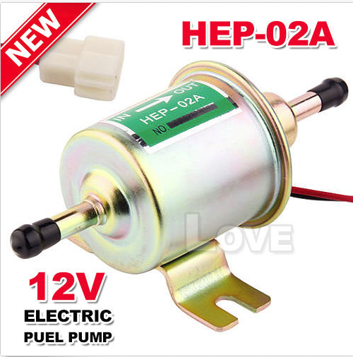
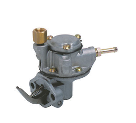
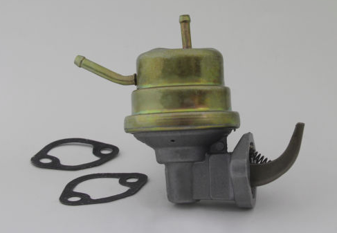
All input trigger, teeth, & synch are critical in an electronic ignition system, but none more so than the synch pulse, as it is the starting point, for setting the sequence & start of the other pulses being counted. Although the synch pulse sensor I created on the timing case cover, with a rare earth magnet, attached to the camshaft sprocket, worked perfectly, I was not happy at all with the amount of work required to install this sensor. Simply put, the timing chain cover has to come off, which can be a frustrating job, if the engine is still in the car, and even if the engine is out, usually means removal of the sump. The whole idea of this project, if it was successful, was that it could be replicated, by anyone, wanting to rid their K Series Rolla of its distributor & points, without any great heartache. My first thought was to pick up this pulse from the camshaft lobe for the fuel pump. Sounded simple ! Replace the fuel pump with an electric one, which worked perfectly. $ 12.00 on ebay, with free postage. Fashion a blanking plate to cover the opening in the block for the fuel pump. Check to see whether a Hall Effect proximity switch mounted through the blanking plate, could pick up the fuel pump lobe on the camshaft. Well it didn’t - reliably. The reason was that the lobe is pretty much a circular, offset from the centre of the camshaft, so didn’t have a sudden on & off, cycle, as you would obtain with a “pointier” lobe of say, a valve camshaft lobe. So I sleep on it, & came up with the idea of reinstating the fuel pump body but “gutting” its internals, and fitting a Hall Effect proximity switch though the lid, sensing a small “button” type rare earth magnet, attached to the centre top of the diaphragm. The casing for the Proximity Switch is a threaded tube, so it would easy to move it up & down to obtain a point, where its ability to produce a pulse was ultra reliable. So here is the finished product. Some of the mechanical fuel pumps used on K Series Rollas, were a sealed unit, which don’t lend themselves to being modified. However, on my shelf, I found a olde dicast fuel pump, which was perfect. You can still purchase these dicast type on ebay. It had a lid, valve section, & an actuator body, in three (3) separate parts. I removed the lid, & middle section, leaving the base & diaphragm intact. I punched out the valves in the mid-section, & then “gutted” the dicast framework for the two valves with a rotary carbide cutter, which took about 30 minutes. I then drilled a 12mm dia hole in the middle of the lid, to take the sensor. I tried several 10mm dia. circular rare earth magnets, but only needed a very thin one, 2mm in depth. This attached itself magnetically to the centre top of the diaphragm. However, I noted the metal centre of the diaphragm was slightly domed. I then removed the diaphragm, & filed the centre piece completely flat. I then reattached the magnet, simply using the magnetic attraction, although intending to Araldite it in place if it all worked. All reassembled, it worked perfectly. I screwed the sensor in, & stopped when the indicator LED on the rear of the sensor was “On” permanently. I then marked the adjusting nut, & rotated it slowly outwards, so that the proximity switch cam away from the magnet (greater air gap). 1.5 turns later, the pulsing stopped altogether (LED Off). I then turned the adjust ¾ of a turn, until the proximity switch was in the midway position, & it is running perfectly, over the full rev range. I was so carried away with how well it worked, I had forgotten to Araldite the magnet in place. I removed the lid to glue said magnet, & it had not moved at all, probably because being so thin; it didn’t have too much mass, & those rare earth magnets are so strong. I will now convert my daily drive KE30 to electric fuel pump, & substitute this Synch Pulser into my car, & give it a good thrashing for a week, to make sure the design is robust. The synch pulser I fitted to the camshaft timing chain sprocket was adjustable, as to where it produced the pulse in the 720 degrees of a full engine 4 stroke cycle. However, using the fuel pump lobe, I didn’t have that luxury. I checked it with the degree wheel on the flywheel, & the synch pulse is produced 71 degrees BTDC No: 1 cylinder, which would make it perfect for other ECUs, that “require” the synch pulse to appear prior to cylinder no: 1 TDC. So after I run it for a week, on my daily, I let you know how it went. I’ll just hook it up to a tacho, & it should read the actual engine revs, divided by 4. Cheers Banjo


-
There are plenty of posts on this site regarding rewires, with lots of useful info. Just search "rewire" or similar. I rewired my KE30 corolla completely, forward of the rear engine bay firewall. Probably the best thing I ever did. Also did the same with all rear lights. https://www.rollaclub.com/board/topic/65882-after-market-ke-light-column-switch/ The Toyota factory body manuals, usually have diagrams of the individual circuits, which are much easier to follow, than those "rats nest" wiring diagrams, you get in most car manuals. The advantage with rewiring from scratch is that you can increase the wire guage & reduce length of circuit path, which ultimately results in less voltage drop issues, & "BRIGHTER LIGHTS" ! Usually, up under the dash is OK, as it is all protected. Adding extra fuses also helps, as Toyota used to often feed several circuits from the one fuse, to keep down the fuse count, which can be confusing. Any specific help you need, just give us a yell. Altezzaclub on this forum, is a wiz on breaking down auto circuits, & issues, so search some of his posts. Cheers Banjo
-
Heavens Jeremy; you've got good eyes. Either that, or you saved the photo, then blew up that particular area, in a vieiwer software ?
-
The first number & letter of the engines serial number is the series of the K motor. 2KXXX 3KXXX 4KXXX 5KXXX 7KXXX The serial number is on the side of the block back from the dizzy.

-
Hi Pete, I guess you watch this video then, every night before going off into Toyota dreamland ? https://www.youtube.com/watch?v=9ltBcBxJ9tQ Cheers Banjo
-
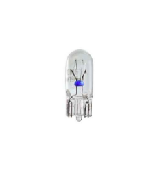
Hi Glenn, I think the bulb you are after in the "wedge" or "T10" type glass bulb, which are widely available. They come in 5 watt & 10 watt versions, & lots of LED versions. https://www.youtube.com/watch?v=NoWU4_Qmeyg Because you are using one in a blinker, you should go for a filament type, rather than the very low current LED ones, as the current of blinker bulbs determines the flash rate of your blinkers. However, you could probably get away with an LED one, as you still have two other filament bulbs on that blinker circuit, all in parallel. Lots on ebay, & very cheap, with free postage. Hope that assists. Cheers Banjo
-
Hi Glenn, I didn't know there was a indicator / blinker on the top of the guard of a KE35 Coupe ? Are you sure you don't mean the indicator / blinker on the outside of the guard ? If so, I'm sure those bulbs are available. I'll nip outside to the shed & have a look. Cheers Banjo

-
Hi Francisco, Have you found that elusive 15 degree difference you discovered, that wasn't there initially ? This is a bit like a murder mystery. i can't wait to find out what/who is the culprit. Did you rotate the engine to TDC No: 1 cylinder exactly, then lift the dizzy cap, & see at what part of the rotor outer end brass arc, the dizzy cap post for No: 1 spark plug was pointing to ? As you've got a points dizzy, you should also be able to visually see where the lobe & points are positioned at TDC. P.S. I always place a white mark, on the bottom base of dizzy, dead opposite No: 1 spark plug lead post. That way, when you can take the cap off, to look at the rotor position, you have a reference mark directly below it. Good luck ! Cheers Banjo
-
Just got an email from TechnoToyTuning this morning, for their BlackFriday sale. On their Instagram site, is a picture of a Te37 / SR5 that lobbed up at one of the meets they were at. Oh, they were an awsome looking, classic, aggressive looking coupe ! Or this one ! https://www.youtube.com/watch?v=lvT8PQTBuRk If you like Levins, then this vid is a good way to enjoy a cup of coffee & relax, . . . and dream ! https://www.youtube.com/watch?v=7csP_Nq1eG4 Cheers Banjo


-
Hi Alon, If you are into the bare metal look; then if you haven't watched this very olde MCM video, you should. Only if . . . . . what not to do ! MCM VW Golf Bare Metal Project Cheers Banjo
-
Welcome Aboard ! We like Liteaces ! They have 5K engines in them ! Where are you located ? Cheers Banjo
-
-
I did a bit of cleaning up, on the collector area, as suggested, & although not using the tie wire, I did make a triangle, using the Bunnings stainless steel ties, which are heaps better than those supplied with the heat tape. I had so much tape left over, I even lagged the front box, just because I had it. Always hard to know how much tape you need, if you've never done it before. For those interested, I ordered 15m of 50mm wide tape. With all that pipe depicted below wrapped, with a generous overlay, I still had 4.5 meters left over. Cheers Banjo


-
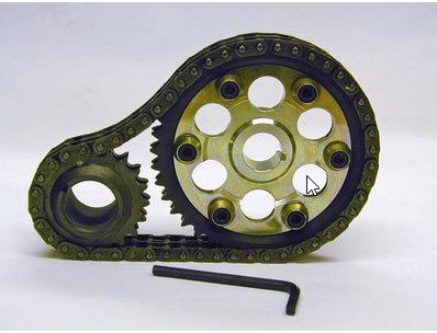
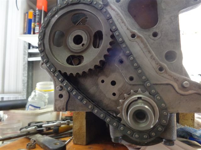
Did your KENT vernier large timing chain sprocket look something like this, or was it one with an off-set pin for adjustment ?
-
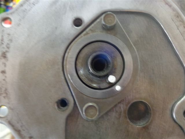
From your latest test, I can pretty safely say, the issue is one of "timing". All you have to do is find where the timing error lies. There are really only two places. The timing chain & sprockets, or the dizzy alignment with the camshaft centre gear. Do you mean by above that the dots on the two sprockets, were both on the outside, & aligned with a line passing through the centres of crankshaft & camshaft ? Even one chain link out in this area, can cause havoc. Was there any special instructions that came with the Kent camshaft ? With the keyway in the crankshaft vertical, at the top, that is at TDC for no 1 & No 4 cylinders. Interested to find out where the error lies. Cheers Banjo

-
I think you have found your problem. In my last post I said, "it may well be too advanced" Do you know how to make a TDC piston stop tool, & find true TDC ? Plenty of details on the net, with videos. https://www.youtube.com/watch?v=PD0ZRc7Dy28 I made one out of an old spark plug. What brand of duplex timing chain did you use ? The small sprocket is keyed to the crankshaft, but the large upper sprocket is aligned with a pin that comes out of the front end of the camshaft. Some vernier type TC sprockets have a number of holes, set distances, either side of the TDC location hole, to advance or retard the valve openings. Are you sure a pin locator was used. It sounds like the top sprocket might have moved/rotated slightly. After determining the true TDC, with the piston stop tool, you may find that the timing chain cover, is going to have to come off, to see where the issue really is. When you assembled the engine, before fitting the head, did you bring the cylinders 1 & 4 to the top of the block, & check that the crankshaft pulley timing mark aligned with the markings on the timing chain case. Is there any chance you used a timing chain cover from a different K series engine ? Their timing marks are not all in the same place. I think you are close to finding the issue, but as we are not in Portugal, it's you who will have to try out all these suggestions. P.S. I was so hoping, the problem would be the dizzy out one tooth, as that is so easy to fix. Cheers Banjo
-
Hi Austin, I have very good news for you. The KE30 auto console perfectly suites the manual conversion. I think I remember cutting away, just the barest amount of plastic. I'll take a pic of mine tomorrow, & post it in your post here. Cheers Banjo