

Banjo
-
Posts
1933 -
Joined
-
Last visited
-
Days Won
95
Content Type
Profiles
Forums
Events
Gallery
Blogs
Everything posted by Banjo
-
That ballast resistor behind the ignition coil should be mounted on the front of the bracket holding the coil, on those two little "wings" with the holes on them. Those ballast resistors get pretty hot, so they need air flow over them, so that's why they are usually mounted up in a free flow air area. Cheers Banjo

-
You shouldn't have one of those 100A fuses between the battery & starter. The big heavy cable between the battery +ve terminal & the starter motor should have nothing else in between. The starter motor current draw, is the highest current drawn by any part of your car. In Winter, it can easily be over 100 Amperes, whilst cranking. Your battery is probably rated at least, for 330 CCA (Cold Cranking Amps). The only high rated fuses needed in your car, are the two (2) fusible links, between battery positive terminal, & alternator, & the other one for everything else in the car. Those "MEGA" fuses are really there for things like fridges, big sound systems, dual battery systems etc. Lets know if it will start now. Cheers Banjo
-
That Fanta Can might be the problem. All that fizzie gas, is making your engine "buurp". Ha ! Ha ! look forward to the pics of the coil. Cheers Banjo
-
Can you take me some close up pictures of the ignition coil. Is it a sports or high performance coil ? Are you using points in the distributor ? I'm a bit concerned about the ballast resistor mounted next to the coil, which is tucked in between coil & mounting point. Your photos of the engine bay, blown up, do not provide me with enough resolution, but I can only see one terminal on the ballast resistor. Cheers Banjo
-
Morning ! Something serious going on here ! You haven't given us a lot to go on, so I'll ask a few more questions, & see if we can narrow it down. I assume by "got a few cracks out of it", you mean the engine fired, or ran for a very short time, then went dead ? Do any other electrical items work, or are all the cars electrics dead ? Lights ? Horn ? Heater Fan ? Etc. Are any fuses blown ? If so, which ones ? Is the fusible link near the battery positive terminal intact ? I am assuming by "no dash lights", you mean no warning lights, like oil & battery/charge lights ? I might have to come across Bayside, & give you a hand. Electrical faults are always simple to fix. The hard part is finding them. You best friend is a multimeter or test lamp. Cheers Banjo
-
Hi John, Welcome aboard ! Most people do those sort of things up as hard as you can by hand, with a normal length spanner. The Gregorys KE30 manual I have here, provides the following torque settings: Spring Front Pivot bolt nut: 55 Nm Spring Front Pivot bolt bracket bolts: 16 Nm Spring Rear Shackle Nuts: 55 Nm Shock absorber Upper Mounting Nut: 31 Nm Shock absorber Lower Mounting Bolt: 31 Nm U Bolt Nuts: 45 Nm Diff Crown wheel Retaining Bolts: 90 Nm Bearing Cap Bolts: 60 Nm If I come across any more, I'll give you a yell, & add them to this list. Cheers Banjo
-

KE20 TE21 1974 Toyota Corolla 1588cc Blowing fuses
Banjo replied to foodrap's topic in KExx Corolla Discussion
Hi Christopher, Big G is right on the ball. Your symptoms indicate either one or both of his scenarios, are an issue in your car. Fairly simply fix. The blown fuses indicate a wire possibly free somewhere, that hasn't been connected, that is intermittently touching chassis, when the car rattles & rolls a bit, whilst starting. Do let us know how you go. Cheers Banjo -
Plenty of wiring diagrams on the Commodore owners website forum. Cheers Banjo

-
I would think the loom is the least of your worries. First you've got to work out how you would shoe-horn a Commodore VS V6 into your Rolla, & all the other structural & brakes/suspension mods necessary to make it all work. Anything is possible, if you watch Custom Garage on 7 Mate on TV, but the amount of planning & cost would be substantial. Cheers Banjo
-
There is a Shannons Show "n" Shine at the Leyburn Motor Sprints in August, if you want to take it for a run up to the Darling Downs. Absolutely great weekend ! http://www.leyburnmotorsprints.com.au/ I'll be there, & will help you polish it. Cheers Banjo

-
I just love your rotisserie; It is so simple ! There are some others on the net that are similar to yours, but use a circular hoop, on small rollers, on the floor, which would make it a bit easier to rotate by hand. The secret, I guess, is to get the centre of gravity of the car body, directly on the centre line of the rotating frame. That would then require minimal effort to turn the frame, with car body attached. Then you can go to the other extreme, as in the following video, where the rotisserie is so complicated, it would take you a year or so to build it. https://www.youtube.com/watch?v=7zIticsQNPw Cheers Banjo

-
Very artistic ! Are you planning on taking your KE20 to shows ?
-
I'm fascinated as to how you achieved this colour co-ordinated hoses & electrical cables. Is it an orange plastic sleeve over the existing HT wiring on the dizzie cap ? Even the twin carbie throttle joiner shaft appears to have an orange tube over it. Is that a windscreen washer bottle in the bottom LH corner of the last pic above ? Cheers Banjo
-
If you didn't adjust the tappets, & the new head gasket is thicker, then that should not result in any valves being permanently, "just off their seats". If anything, the tappets should be a bit noisier, & "clicky", as the gaps should be slightly wider. Cheers Banjo
-
I'm assuming you haven't changed anything relative to the carbies, and you have adjusted the tappets, when you put the head back on. My guess is that you have a timing issue, when you reinserted the dissy, or there is an air leak on the induction side somewhere. I would try removing the dizzie, placing the engine at TDC No: 1, as described here in various posts on this forum, & refitting the dizzie, ensuring the rotor is pointing to spark plug no: 1 HT wire on the dizzie cap. Your photo above indicates the HT cables on the dizzie cap are connected in the right 1,3,4,2 sequence. You might simply be one tooth out, when you put the dizzie back in. Let us know how you go. Cheers Banjo
-
Love the 8 position rotisserie you made up & used ! Just a brilliant & simple concept. The power output from another K series motor you put in it, will depend on what you intend to do with it, "driving wise", and whether your car rebuild has been stock, or whether you have upgraded the suspension & braking system, in any way. 100hp might be a tad too much for a daily drive; and involve extensive K series upgrade & cost, to accomplish. The final pictured result above, is one very sweet looking KE20. Congrats ! Cheers Banjo
-
4k timing chain broke, great fun replacing.
Banjo replied to rebuilder86's topic in KExx Corolla Discussion
Hi Graeme, If you can bribe your bank manager, they are still available. http://www.motorsport-sales.com/index.php?main_page=product_info&cPath=320&products_id=3721 You'd be paying for a few fines, if you popped that one in your girls Rolla ! http://youtu.be/rbovoGOWByk Cheers Banjo
-
4k timing chain broke, great fun replacing.
Banjo replied to rebuilder86's topic in KExx Corolla Discussion
That's why I asked earlier in this thread, whether the boring out of the block, to fit the liners, ever broke through into the water jacket, in the area you are mentioning. I once read, that modified engines for 1/4 mile dashes, just fill up the water jackets with "Araldite", or something similar, to prevent the cylinder walls flexing, when they are bored to the limit, & become very thin. Cheers Banjo -
4k timing chain broke, great fun replacing.
Banjo replied to rebuilder86's topic in KExx Corolla Discussion
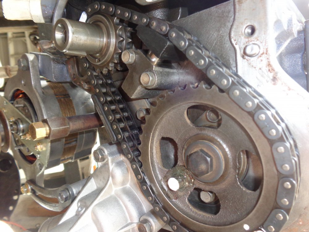
Hi Jeremy ! So where is the missing link ? Did you retrieve it, or is at the bottom of the sump ? To my knowledge, the chain is all one piece, with no removable link. That's why it is necessary, when fitting, to attach the chain, to the two sprockets, then slide them onto their respective shafts at the same time. The joiner pins in your pics, don't show any sign of wear, adjacent to the missing link, if it was rubbing against something. Was that how you found it, or was there some broken bits, still attached to the chain. I'm interested, as I've never heard of a K series chain breaking. Cheers Banjo -
4k timing chain broke, great fun replacing.
Banjo replied to rebuilder86's topic in KExx Corolla Discussion
Hi Jeremy, Thanks for that info. That's great, & I'm now much better informed. Do they also produce these cylinder sleeves for the 5K, which has have a nominal bore of 80 mm ? The advantage of oversizing the piston & bore, when an engine gets to that point in life; is that you finish up with a slightly larger swept volume in the cylinder, which with the same head & gasket thickness, increases the C.R. a bit. If you skim the head at the same time, that also increases the C.R. P.S. Actually, I just looked up the Toyota factory "Yellow Bible", for the 2K-3K-4K-5K, & it says you can oversize 3K & 4K blocks to 1.0mm, but only 0.50mm for the 5K. That indicates, that to fit the sleeve, with a 2mm wall thickness, you would have to bore the block cylinder out a whole extra 1.00mm, in excess of the normal maximum o/s bore size of 1.0mm. If that doesn't result in breaking into the water jacket, then there appears to be quite a bit of "meat" in those cylinder walls, in the block castings. Cheers Banjo -
4k timing chain broke, great fun replacing.
Banjo replied to rebuilder86's topic in KExx Corolla Discussion
How wrong those "deriding" individuals; (time has proven), they were to be ! -
4k timing chain broke, great fun replacing.
Banjo replied to rebuilder86's topic in KExx Corolla Discussion
Very interesting, how local conditions in a particular part of the world "spawn" a whole different way of fixing an everyday automobile issue of the engine bore eventually wearing out. I had the house to myself last night, as wife was interstate visiting son, & daughter was working all weekend, & staying with friends. So I "binged out" on the complete 5 episodes of MCM of the Honda VTEC B16 engine transplant, into the Japanese Mini Minor, which is a classic. https://www.youtube.com/watch?v=NQ8RLM8eWRU So I'm Googling after that marathon, on the difference between Honda & Toyota variable valve timing techniques VTEC vs VVT-i, & all the other variates of those that have come since. I also Googled which was the better, & that was a good read, from both sides of the perennial argument. In doing so I came across a website, which lists all the Toyota engine variants that were offered to Russian Toyota customers. http://toyota-club.net/files/faq/03-08-16_engine_eng.htm It describes the good & bad points of each engine series marketed there in Russia. There was two particular comments, that drew a smile. The other was the comment, regarding our beloved K series of Toyota engines. So that got me thinking about another series of Toyota engine in the 1.3 - 1.8 Litre range that could ultimately be used to transplant into a KE Rolla, with all their later technology advantages. I've broached this subject before, when I fell in love with the NZ-2FE & NZ-1FE engines used in the Echo & Yaris cars, which after 2004, had a pretty good VVT-i setup. The problem with all these engines, is that they come from east-west front engined cars, & placing them in a north-south orientation, requires a very difficult, if not impossible requirement, when it comes to a gearbox adaption, & engine mounts. Maybe, simpler to drop in a late model MX-5 engine + gearbox, and be done with it. Jeremy's comments regarding the sleeving of K Series engines in the Philippines, reminded me that the NZ-1FE Toyota engine is a sleeved engine, in an aluminium block. I've never really thought about that, as I've never had to sleeve an engine in my whole life. A little research on the NZ-1FE engine, appeared to indicate, that the engine cannot be re-sleeved, after the bore is finally worn out. According to some comments I read, once the NZ-1FE engine bore is worn out, the block is a throwaway. What really surprised me, that Toyota originally, apparently, only designed this particular engine series, for a life of 200,000 klms. As my daughters Echo has clocked just over 195K klms, that point is fast approaching. However, maybe Toyota were being too conservative, as forums indicate, many Echos & Yaris Toyotas have achieved 250K - 350K klms with no major mechanical engine repairs, other than regular service. I would believe those figures, as I did a major service on my daughters Echo last weekend, after changing the clutch, (which is another story), and found oil colour, spark plugs & everything in extremely good condition. I whipped the induction idling actuator off it, & soaked it, to clean it thoroughly, as these do become an issue, & there was a belt that squeaks, for the first 5 mins of run time, which indicates it is on the way out. So it will probably do another 20-25K klms again this coming 12 months, without issues. Here's an interesting comment regarding the common Echo/Yaris squealing on a cold start up, that I am experiencing. The sound in this video, is exactly what I'm hearing. https://www.youtube.com/watch?v=HRrVMtyIqIY It is not the battery; that was brand new last week. But getting back to the sleeving of K series engines. I think oversized pistons come in sizes up to +50 thou., where I would imagine the cylinder walls start to get a bit thin. Could you then fit a sleeve, & does boring the block out, to take the sleeve, break through into the water jackets ? As I say, I've no experience with sleeving K series engines. Also, as sleeves, then allow standard piston size to be fitted, can you then re-bore a sleeved engine, to take oversized pistons, after the sleeve has worn out to its limit ? Any comments or info appreciated. Cheers Banjo -
4k timing chain broke, great fun replacing.
Banjo replied to rebuilder86's topic in KExx Corolla Discussion
Hi Jeremy, I've seen some loose timing chains, on K Series motors, but never a broken one. Have you still got the chain, & can take a picture of the break ? Was there any indication as to why it broke ? P.S. Just be thankful you didn't have a timing chain like this one break. This is a V12 Lamborghini Diablo engine from 1993. Cheers Banjo
-
4k timing chain broke, great fun replacing.
Banjo replied to rebuilder86's topic in KExx Corolla Discussion
Hi Jeremy, You can buy the whole timing chain kit on line, which includes both sprockets & tensioner & guide. There are some good aftermarket ones available like Rollmaster, but I'm sure in your part of the world, you have access to more Asian ones. I've always upgraded all my K series engines to double row timing chains. Eventually, the chains stretch, & the rubbing block on the tensioner wears down to the point, where the tensioner at full extension, is no longer effective. I've even heard & seen a K series engine, where the timing chain noise was so loud, as it was slapping against the inside of the timing chain cover. Removal of the cover, & the marks on the inside of it, confirmed this. Even my olde 3K engine, I'm converting into a coffee table, has a double row chain on it. I think they were standard on the 3Ks, but then went to single row on 4K & 5K engines. Seems strange change. Maybe someone will correct me on that. Cheers Banjo
-
4k timing chain broke, great fun replacing.
Banjo replied to rebuilder86's topic in KExx Corolla Discussion
Hi Jeremy, Great description ! I could also smell & feel the cow poo ! Been there, & done that, but not for a broken chain, but to replace the front crankshaft seal in the timing chain cover. Were the very front two (2) sump bolts, actually bolts, or threaded studs with nuts ? I can remember, mine being nuts & threaded studs. The studs were too long to allow the cover to clear & come off. There was just enough room on mine, to put two (2) nuts back to back, on the stud very tightly, to allow me to extract the whole threaded studs. Needless to say, they were replaced with bolts. Probably a reasonable amount of room in your "jeep" from pics you have posted in the past, of that area. Not much room in a Rolla, although, after removing the radiator & sump stone guard, it is possible, but you finish up with a kinked neck, for a day or so. Regarding the the oil squirter feed for the timing chain. Yes there is one. It is a small hole drilled into one side of the timing chain tensioner, which works off engine oil pressure. It is directly in line with the chain. It doesn't have a "squirter tube or spout" fitted, like some older car engines. It is just a little hole. They can block up. I've always dissembled the tensioner, soaked in in kero overnight, & run a straightened paper clip wire through it, until it was clear. Don't be tempted to drill it out, as it's size is critical, as you don't want to bleed tensioner oil pressure away from the tensioner piston. P.S. Was the timing chain that broke, a single or double row type ? Cheers Banjo


