

Banjo
-
Posts
1933 -
Joined
-
Last visited
-
Days Won
95
Content Type
Profiles
Forums
Events
Gallery
Blogs
Everything posted by Banjo
-
Hi Graeme, I'll put my hand up. I had to Google "Corey Hart" to see who he is, & what the reference referred to. Brilliant Dave !
-
Second happy ending to this story ! Top marks for Altezzaclub & The Spirit Man for getting this one right. Cheers Banjo
-
The secret is out ! Kyogle area. The making of the SCA latest oil ad. If you are are ever in the area, please explore this valley & area. It is just beautiful ! https://www.supercheapauto.com.au/blog/all/kyogle-council.html?utm_source=edm&utm_medium=email&utm_campaign=MF_SCA01_2019_WK18_CAT & another . . . . https://www.youtube.com/watch?v=k-eMH3klU2w Cheers Banjo
-
That's brilliant ! Probably a little bit too bright. I got a roll of those LEDs. They are great. Use them for various lighting requirements. You can build a simple dimmer for LEDs, using a variable Pulse Width control. Plenty of circuits on the net. https://www.youtube.com/watch?v=n48GemL7tsc Cheers Banjo
-
Here's a link to one I remember recently. https://www.rollaclub.com/board/topic/73225-smarten-up-your-dash/?tab=comments#comment-708509 Here is another . . . https://www.rollaclub.com/board/topic/51690-rosie-the-ke55-rolla/?page=4&tab=comments#comment-540580 Just Search Rollaclub above field for LED or T10, & a few will come up. Cheers Banjo
-
Welcome aboard ! Wow ! You have a lovely Rolla there, & are a very lucky man, going by it's very good condition. How long have you had it ? Do you know it's previous history ? (Little olde lady etc. ?) Looks like you've got another future Rolla enthusiast there in the making ? Keep the pics coming, & fire any questions you have our way, as there a lot of people on here, prepared to offer good advice. I've got a KE30 2 door, a little bit older, in the same "baby pooh" colour, as my wife calls it. I'm on my third Rolla now. I've had a KE35 2 door coupe; KE55 2 door coupe; & now the less seen KE30 2 door sedan. They are so reliable, & anything that does go wrong, can easily be fixed, as I'm sure you've found. Easy to work on. Only nasty is rust, when they get to be 40 years olde, particularly if you are by the sea, as I think you are. As long as you can keep it out of the structural areas, underneath, it should be alright. Cheers Banjo
-
Oh dear ! If water creeps in behind that floor sound deadening stuff, that Toyota painted on 40+ years ago, you often can't see any rust, until you scrape it off. Hope that's all the rust you find ! I've been looking for a black console I was sure I had. Couldn't find it, which you would understand, if you saw the back of my shed, where I keep all this stuff. After looking again today, I suddenly remembered, I sold it to a fellow Rollaclub member here in Australia, about a year ago, as part of a whole kit of bits & pieces he bought off me, for his resto of his Rolla. So sorry, I haven't got a console for you. Put it up on the forum under "Wanted to Buy" & see if you get any response. If I do come across one in my travels, I'll let you know. Looks like it might be a little while, before you arrive at the fit-out part of the resto. Good luck ! Cheers Banjo
-
Been raining here, but sun out today, so will go have a look in the shed, & see what I have in the way of black consoles, & let you know. Cheers Banjo
-

What RPM to drive when facing oil problem?
Banjo replied to rebuilder86's topic in General Mechanical
Hi Jeremy, The thing I like about mechanical systems, of any description; is that they more than often give you a warning, in advance, that something is amiss, or on the way out. Unfortunately, electrical & electronic systems are often not as providing, & just go bang, or bust, or splat ! If you suspect something, whilst driving, I always turn the radio off, close the window, to remove wind noise, & listen carefully to the engine, under different load conditions. Congrats ! Elon Musk is current selling tickets to space. However, not 4K powered, which I know will disappoint you ! https://www.afr.com/leadership/innovation/when-where-and-how-elon-musks-spacex-plans-to-colonize-mars-20181016-h16qay Cheers Banjo -
What RPM to drive when facing oil problem?
Banjo replied to rebuilder86's topic in General Mechanical
Hi Jeremy, I read your post an hour ago, but have just stopped laughing long enough to respond, after reading the reference to the "4K Powered Mars Rover". Been there done that ! Not Mars, but in outback NSW (dirt roads), with a very sick engine, on the second day of a 10 day excursion. Low oil pressure; Summer; But worse than that, was the tick, tick, tick, tick, of a big end on the way out. Filled it up with the thickest oil I could get hold of, & finished the trip (3000 klms), & got the car back to Sydney. I remember contemplating what you are presently, & asking myself the same questions. What worked for me, was to drive which ever, which way, to put the lowest load on the engine. That meant lower speeds & light on the pedal on flat long straight roads, & revs & lower gears to lighten the load, when there was a hill. Lightly loaded engines don't run as hot. Never used one of those oil additive products, that increase the viscosity. Sounds good. Assembled an engine wet once, with a oil made up of 50% engine oil, & 50% molybdenum disulfide. Rubbed it into the bores, and all bearing surfaces. Worked a treat ! The MDS is very dark in colour, & 10 years later I dissembled the engine, & was washing the bearing shells & bore with a mixture of kero & petrol, & the cleaning fluid was going very dark, very quickly, until I realised the MDS was being flushed out of the grains of the metal. Cheers Banjo -
Nice work place ! Wish I had that much room around my Rolla, under cover, to work on it. You've even got a lounge there in the background to sit on, when you need a break ? Cleaning back the underside for painting, can be a happy, or unhappy time, depending on what you find, when you strip away, back to bare metal, after 40+ years. Good luck ! Banjo
-
Is your KE35 a manual or auto gearbox ? The consoles are a bit different. Heaps of them here in Aussie. Off memory, there are only two basic colours. Black or Beige. They are bulky but quite light, so maybe posting one over to you in Portugal could be a better option, & give you more time to get on with other things. Have you had the engine running as yet ? Cheers Banjo
-
Rear of front mudguard, splash shield. Nice car ! Great starting point to have a basically rust free shell. Good luck ! where are you located ? Cheers Banjo

-
I've followed these guys from the start, & "the ride/s" has been quite amazing. Don't know whether you have ever watched this video, but there is another side to these guys. This one involves a Corolla, so check it out ! https://www.youtube.com/watch?v=Z7-ZTTqMW6M Brings a tear to my eyes, every time I watch it. Cheers Banjo
-
Not quite motor sport, but some could argue ? You've got to watch this video, from SCA, & our two friends Marty & Moog, from Mighty Car Mods. Watched it, & recognised the setting, as it's a road I use it quite often, as a short cut/scenic drive from Beaudesert to Grafton, via the Lyons/Lions Road just north of Kyogle in NSW. https://www.youtube.com/watch?v=1JPm23WpjqY&utm_source=edm&utm_medium=email&utm_campaign=MF_SCA01_2019_WK15_SW Cheers Banjo
-
Hi Rob, I first laid eyes on this particular little Morrie Minor tow truck, at the All British Car show in Sydney, back in September 2016, which is amazing. Nearly 2000 cars ! As I was looking at it again, in Queanbeyan, a Japanese man came up, & was looking at it. He asked me what it was for. I said for towing a broken down car. He was quite bewildered as to how it lifted a car with a hook. He thought all cars were put on tilt trays, or had clamps that went around the front wheels. I pointed out, that this is how it used to be done. He looked carefully at the capstan, & asked where is the motor. It had none, as it is hand wound, with a crank handle from the outside, which pokes through the hole "indicated" in the pic. below. I mimed how it was done, & he walked away laughing & shaking his head. Cheers Banjo

-
wiring Need help wiring sr20det Into ke55 corolla
Banjo replied to NathanKEnut's topic in Car Electrical
That's brilliant, but also daunting, when you consider how much time is involved. https://www.youtube.com/watch?reload=9&v=QBXT1sHP92w However, a simple engine swap, is not as big a job, as our two friends at Binky project undertook, with a "complete" electrics swap. An engine swap project can go very sour, if the electrics are wired in roughly, besides not looking professional. Unreliability is the result, & your NRMA or RACQ roadside man is not going to be a great help, if your car won't go, on the side of the road, in the middle of nowhere. Having done several wiring harnesses, where I have made them up from scratch, the secret is to do one bit at a time, & don't rush it. One of the big advantages of making up your own harness is, that you can increase the size of the wiring used, which reduces voltage drops in the system. Cheers Banjo -
I can't believe a reputable company like Permatex would allow a video like that to get through. That is terrible ! Looks like they gave the instructions to a video marketing company, who didn't have a clue. The oil pump reassemble is incredible. I've never heard of putting a gasket on an oil pump. I've never ever done so, on any K series oil pump, I've reassembled. Here's a better video, although, I still believe he is a bit heavy handed, with the silicone. https://www.youtube.com/watch?v=UXN4FqQH-xM Thanks for your thoughts. I'll go get something generic this afternoon, & let you know how I go. Cheers Banjo
-
Had my 5K sump off at the weekend, so I could refit the timing chain cover, after fitting a dual timing chain. The sump gasket seal had no leaks at all. When I removed the sump & gasket, I noticed that the previous mechanic, who had replaced the sump & gasket, had used three little parallel narrow beads, of what looked like a "bright orange silicone sealant" on both sided of the one piece gasket. I was impressed how well the seal had worked ! I've never been a great fan of silicone sealants, as I've heard & read so many bad/sad stories of users, over doing the application of the silicone. When the two (2) surfaces are brought together, the sealant "squishes" out on both sides of the gasket. Any excess on the outside, can be easily wiped off, but the excess on the inside, can bead & drop off, over time, into the sump, & block off oil pump pickups, or worst still, get caught in oil ways, & starve the bearings. This is more common with "make a gasket" RTV (Room Temperature Vulcanising) sealants, where the sealant, is the gasket, so users become over generous with the sealant. Now most of the automotive silicone sealants are marked as, Make A Gasket. In my case I'm using a new sump gasket out a Permaseal gasket kit. It looks & feels like a rubber one, but I suspect it is made of a composite material, as it stretches a bit more than a pure rubber one. So what is the best silicone sealant I can use, to replicate three narrow beads of sealant on both sides of the gasket ? Can the "Make A Gasket" sealants also be used as a seal to the gasket, or do they have a different composition, because they are used as the gasket? I've always been an aviation gasket adhesive user, for a long time, & have never suffered an engine oil or water leak, but I will admit, it's a real pain cleaning off the old aviation goo sealant, before putting something back together, so I'm prepared to give my sump gasket the silicon seal treatment, so would like to hear other forum users thoughts & experience. Cheers Banjo
-
Love you work ! Always attention to detail. Never apologise about the use of zip ties. I never go anywhere without a resealable plastic bag, with a selection of different lengths therein. In the glove-box, in my briefcase, in my tool box. One of the most useful everyday inventions ever made. I recently was given a packet of special wide heavy duty ones for water hoses on automotive engines. I've used them on one engine. One size fits all size hoses ! Just zip it up & cut off the excess. I believe they are using them on the latest model Volvo cars as standard. Cheers Banjo
-
Thanks ! Is this the one ? They are under $ 100 on ebay, so if I need one permanently, & it is quieeeet, it might be the go,. Cheers Banjo
-
Drove a Toyota Echo from Brisbane down to Canberra at the end of the week, for my son, & spent the weekend in Canberra. The Victorian Morris Minor Car Club, had a rally, up & back from Melbourne, with the weekend in Canberra. Came across this beautiful collection, on show last Saturday, in a Queanbeyan park. https://1drv.ms/f/s!AhTw-QJW1b_6j0-3qwSBFTBR2OZ9 Enjoy ! Cheers Banjo
-
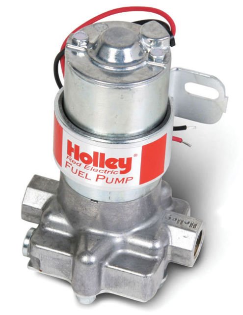
Tah All ! It's only for an experiment, so $ 16.00 incl. free postage, won't break the bank. Not too worried about the noise, but have noted the suggestion of an "isolated" mounting. How do they work ? Are they some sort of rotary type ? Looks like an electrical transformer ! My only experiences with electric fuel pumps, are with those early SU tick, tick, tick, ones, with a diaphram, that slowed down to a very slow tick, when you were idling. Cheers Banjo
-
Well it's the weekend, & I've some time to work on programming the crankshaft positional sensors, I've installed, to create a sequential ignition system, which is totally independent from the ecu, which does all the engine performance "timing calculations". So far, the results are exceeding my expectations, & electronically, it is not that difficult. I'm seriously thinking of implementing another form of "synchronisation sensor", rather than the Hall Effect sensor, I've detailed above, that is fitted to the camshaft timing chain sprocket. Don't get me wrong, the timing chain sprocket sensor works very well, but is time consuming & a bit difficult to implement. Because the synch signal has to produce a pulse once every two revolutions of the crankshaft, it must be produced from the camshaft timing. The easiest way is to simply use the existing dizzy points, or with an optical/Hall Effect sensor fitted therein. However, this project is about getting rid of the dizzy totally, so that's not my option. The other point on the camshaft, where a signal could be obtained is the fuel pump's eccentric "operating lobe", on the camshaft. This could be a very easy modification, if it works. Remove fuel pump. Make little plate to cover hole in the block. Drill hole in plate. Fit Hall Effect sensor that will detect the tip of the eccentric lobe. Hey presto ! Now I haven't got a fuel pump, so my idea is to just fit an electric one, so I can see on the road, in real-time, how reliable a signal would be from this source. What type & brand, of electric fuel pumps have Rollaclub members fitted, that have proved reliable ? Of those of you who have had fitted an electric pump; did you fit it in the engine bay, or down in the boot somewhere, so the whole fuel line from rear end to carby is under pressure, rather than suction ? Very interested to hear anyone's thoughts on electric fuel pumps fitted to N.A. Rollas. Cheers Banjo
-
Luv it ! Actually I've got a spare Corolla "honeycomb" grill in the shed, I could do that with. A great idea might be to suspend it from the ceiling, rather that mount it on the wall ? You might have just started something here ! Cheers Banjo


