

Banjo
-
Posts
1933 -
Joined
-
Last visited
-
Days Won
95
Content Type
Profiles
Forums
Events
Gallery
Blogs
Everything posted by Banjo
-
Hmmm ! Not looking good. When you "rebuilt your 5K" did you . . . . Skim the top of the block ? Skim the head ? Repair any corrosion around any of the water jacket transfer holes in the head ? Use a new head gasket with built in sealant bead around the water jacket transfer holes ? Ensure you fitted the very heavy/thick washers back under each head bolt ? The LittleRedSpirit man's suggestions are now your best suggestion, of getting to the source of this problem, now that we have ruled out the other more common, easily fixed ones. Let us know what you find. Cheers Banjo
-
Hi Scott, Can't really say, as mine is not in a closed situation, as you can see from the pics. Has got rid of that "tinny" sound you get from a bare exhaust pipe, so probably changes it's vibration frequency a bit. I put it on to basically stop me burning my leg, when walking around the test engine, & not concentrating, because I was intent on something else. Cheers Banjo
-
Hi Viterbo, Just looking at your pic of the Pimera radiator. I'm presuming that your line to your overflow/expansion bottle, is connected to the spout circled on the RHS of the above picture. Is that round bit directly below where the radiator cap fits on, a "bleeding" point for the coolant ? Looks to have a hex socket in the plastic, so could be screwed out. Is the point where the spout comes out of the Pimera radiator the same distance below the top, as the spout on the K Series radiator ? If the new Pimera radiator cap, does not solve the problem, then the question arises, why is the system not pressurising, when you unlock the radiator cap after running, & there is no pressure exhaust obvious ? That can only mean that the coolant system is not sealed elsewhere, & is not allowing the system to pressurise. Have you hooked up a cabin heater or anything other coolant line elsewhere ? There aught to be a leak displaying somewhere. If no, then the only other explanation can be an internal leak, within the engine itself., which is serious. Check oil level & discolouration etc. I do hope the new Pimera radiator cap solves the issue, because if not, I would not run the engine, until you solve the issue, for fear of damaging the engines internals. Cheers Banjo

-
Think we might be close to solving this. There are lots of different radiator caps, & it's "pulling a long bow", to expect an early K Series radiator cap, would work perfectly with a later model Nissan Pimera. Let us know what the results are. Cheers Banjo
-
I just noted this comment of yours . . . . Is the radiator cap you are using, the one that came with the Pimera radiator, or are you referring to the one from your original K Series radiator ? I'm starting to suspect, that your coolant system, is simply not pressurizing. After the engine has been running for a while, but before the overflow starts, have you removed the radiator cap, by hand, & noticed that there is a "pressure release" ? Cheers Banjo
-
As you have been very careful filling the engine with coolant, we can assume there are no air locks inside the block or head. Is this overflow of coolant, you are experiencing, happening when you are driving the car, or when stationary ? What is the ambient temperature where you are located ? I suggest that you disconnect the thermo-fan, so it can't switch on. Remove the radiator cap, start the car, & let it run, in a stationary position, to allow the coolant to heat up. Look down the radiator filler neck, & the coolant should be very still, until the coolant reaches the point where the thermostat, cracks open, at around 85-87 deg C. When this point is reached, little bubbles start to appear at the filler neck, & then the water starts to move & flow, as the thermostat opens further. "Not sure what you mean by " But that means the radiator is not full." The radiator should always be full in a totally closed pressurised system. As the coolant heats up & expands it increases in volume & pressure. That extra volume increases the pressure in the coolant system, & the radiator cap opens, & allows the excess coolant into the "expansion" tank. The coolant system & radiator still will be full of water. When the engine cools down, the reverse happens, & the vacuum created within the coolant system, opens the second return valve in the radiator cap, & the coolant in the expansion tank, is sucked/drawn, back into the coolant system. Most coolant overflow/expansion tanks have a mark on them showing max. This is usually about 2/3 or 3/4 of the capacity of the tank. This is when the coolant is cold. Therefore the free capacity of the expansion tank, is the volume provided for expansion overflow of the coolant. It does not require a great volume. It is important, if you are using the K Series overflow bottle, that the tube on the bottom of the cap, is not missing. Unless the overflow line is below the level of coolant in the expansion tank, it cannot draw the coolant back into the engine. That's why a lot of coolant / expansion tanks, have the overflow line connected at the bottom of the tank, so that it is always covered by coolant. Cheers Banjo
-
Can you explain to me why the Nissan Primera has two caps, (one for the radiator, & one for the expansion tank), & why the expansion tank cap would open at a higher pressure than the radiator ? As the overflow, from the radiator, usually only goes to the expansion, or overflow tank, I can't see why it would need a a second cap, & why it would be at a higher pressure rating. As you are using the original K Series overflow bottle, which does not have a pressure cap, I can't see that being an issue, unless your existing radiator cap is faulty. Cheers Banjo
-
Hi Viterbo, The blocked coolant holes at the front of the head gasket, are certainly designed to direct more flow to the rear of head, which has always run hotter than the front. I fixed this K Series issue up, but putting in an extra return path to the underside of the thermostat, from the rear of the head. I would definitely check the radiator cap, & maybe take out the thermostat, & test it's opening in some hot water on the stove; carefully noting the temp, at which it cracks open. I couldn't see from your pictures, whether you are using the original mechanical fan, or whether you have a thermofan. With a radiator that large, the coolant temp should be kept in range by just the "ram" effect of the air passing through it, whilst driving. My thermo-fan rarely comes on, as I have an LED on the dash, that illuminates, when the fan comes on, if the temp, goes above 95 deg C. Cheers Banjo


-
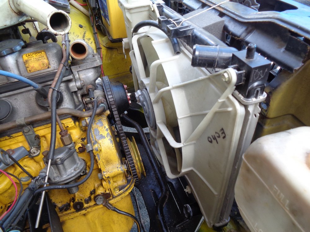
Hi Viterbo, Interesting issue, to which there must be a simple solution, but I can't quite put my finger on it as yet. I did a similar modification, but I didn't use the Nissan radiator, as although it had the inlet & outlets in the right places, it was too big. I used a Toyota Echo aluminium radiator, & the results were exceedingly good. The Echo radiator, is very close to the original size of the K series radiator. The aluminium radiators are so more efficient than the old brass ones, that my thermo-fan rarely comes on. Usually, 4-5 minutes after I have stopped, & turned the engine off, after a "spirited" run. I can imagine your engine maybe over cooling, if there was no thermostat fitted, but not overheating. Have you taken any measurements of coolant temperature around the engine ? Did the head gasket coolant holes line up OK, so the flow between block & head, was not impeded ? Does this standard expansion bottle overflow water feel really hot ? Have you simple tried a bigger vessel, in place of the existing plastic bottle ? On the Echo radiator, I used, the overflow/expansion bottle, which is part of the radiator shroud. It was much smaller than the original K series, so I was initially concerned is might be too small. It was not an issue at all. I look forward to your answers to my queries, so you can get to the bottom of this. Pretty sure the answer is going to be simple. Cheers Banjo.


-
Hi Simon, Welcome aboard ! First let us know where you are located. Back in the 70s & 80s, some Corollas were not imported complete. Some were manufactured in the local country, from parts, & often painted locally. Therefore if paints were sourced locally, the colours could be slightly different from country to country. That was the case here in Australia, where Rollas were assembled at AMI in Melbourne, & used local paints. Post us a picture of your car. If you believe it has never been repainted, & we know it's origin country, someone on here may well be able to assist you. P.S. A good "paint shop", should always be able to match your existing paint colour. Have a look at this website, which lists many of the Toyota paint codes. https://www.uniquecarsandparts.com.au/colour_codes_toyota_A-G.php Cheers Banjo
-
Hi Graeme, I've had one of those for a while now. Gets rotated around my cars. The useful thing about mine, it can alarm you, if you hit a speed limit (like 80 klm/hr) so you don't get caught driving around the city, where speed limits are constantly changing. There is a strip of road near my place that changes 5 times in about 1 kilometre. Does yours alarm ? Cheers Banjo
-
The mind boggles as how the exhaust & headers are going to look like, with the turbo mounted way up there high at the front ? Good luck, & keep it posted on here. Love people who are passionate, (or bored), & take on ambitious projects, that present challenging engineering exercises. P.S. Maybe it is just sitting there to tell us, it is going to have a turbo. Cheers Banjo
-
My wife's 2009 Corolla, gets regular wheel & tyre service at Bob Janes, where they keep tabs on it, & have full computer records of everything they have done on the car, & odometer readings at each service. My wife's car, like all our Toyotas, are fitted with Pirelli Cinturato tyres. On her last set of new tyres, fitted about 6-7 months ago, they informed me, that my wife, is the second highest listed driver on that branches records, for mileage out of a set of tyres. She achieved 94000 klms. She was pipped by another lady at Jimboomba, who only drives Jimboomba to Browns Plains return each day, & achieved 96000 klms. Cheers Banjo
-
I got some Loctite Super Glue for plastic today, so will have a go at fixing the broken radio surround on my BMW over the weekend. I'll let you know how it goes. Cheers Banjo
-
Hi Graeme, Saved your photo of wheel alignment report, then zoomed in, but not enough resolution to read very clearly. Looks like +ve camber on both sides. See if you can take a photo with a bit more resolution. Cheers Banjo
-
Hi Graeme, Having taken a long time to get my front suspension right, on my KE30 2 door sedan, a few years ago, I learnt a lot, from research, & the end results of changes I made, on the alignment setup, at Fulcrum at Browns Plains, because Darryl there, was a Rollanut. (Unfortunately, our mate Darryl pasted away with cancer, in January this year) The Rollas of the early 70s were assembled/stitch spot welded in Melbourne, & the jigging left a little to be desired. They were not all dead straight when they came off the line, & as Coln says, the only adjustments were toe & caster adjustment. Anyone who has jacked up one corner of a KE, has well realised, that there is a lot of torsional give in the KE bodies. (My 2 door pillarless KE55 Coupe, was a shocker for torsional twist.) That's why those that drift them, seam weld the bodies from one end to the other. Over the years, the bodies find a new position & attitude, but no more so, than on the front strut towers, which are not tied together at the top. Hence why it is common, for stays to be fitted between strut tower tops & also bracing back to the rear engine firewall. In addition to that, cross ply tyres were about the only option in those days, & the camber required was straight up & down. A big fat zero. However, with radials, a bit of negative camber can add a lot of stability to the steering, as McPherson strut front ends, have always had a few quirks. However, from my experience, the maximum negative camber, you can apply to a KE series for normal everyday driving, like your girls car experiences, is about 1 deg. I've settled for 0.6 deg, & the car now behaves much much better than it originally did. No shimming ! The problem with providing negative camber, is that you either make the LCAs longer, or pull the top of the strut back inwards. Unfortunately, the KE30/35/55 series used large diameter springs, & there was never much room to bring the top of the strut in, whether you fitted T3 camber adjusters, or like Altezzaclub suggested, slot the holes & weld some washers onto the top, to give some strength. However, the KE70, used the smallest diameter coil springs on the front end of any of the early KEs, & therefore Graeme probably has a little chance, of introducing a bit of negative camber, unless you fit narrower springs. I actually converted my KE30 front struts to accept the KE70 coil spings, so the narrower strut/spring assembly, could lean back further, without touching the strut support inner turret wall. The other way to get a narrow strut profile, is to go "coilovers", as the springs used on them are not very wide. It is a very well worth while modification, to achieve a better controllable front suspension. Castor adjustment, on KEs is probably described, as screw the rods up, as much as is possible. I'm not suggesting that camber adjustment is the only contributing fact. Good LCA ball joints, steering ball joints, & that all important steering idler pivot bushes, & wheel balance, all contribute. From my experience, all McPherson strut design front ends, rely on very good wheel balance, for smooth & stable front end geometry. P.S. Never neglect the misalignment in the body from front to rear. Up to 10mm is quite common, & I've followed a number of olde KEs over the years, & seen the noticeable slight crabbing action. Cheers Banjo


-
Hi Johno, Search "R31" on this forum, & you will find every mention of R31 struts. Here is the thread I was referring to . . . . . . https://www.rollaclub.com/board/topic/11306-brake-upgrade-for-ke20/?tab=comments#comment-159824 The link to the original Bananaman post on Toymods website, appears to be broken or incorrect. Go to the Toymods website, & register, & search Bananmans posts or search R31 struts. Someone else on here might have copied Bananman's post & can add it to this thread. I'll add links to any other references, I find. https://www.toymods.org.au/forums/threads/34997-strut-inclination-angles-info You can do plenty of brake upgrades on the stock LCA and steering arm, using a variety of struts. Here is a link to all of Banaman's posts on Toymods. If you search through these, you'll probably find what you are looking for. http://forums.toymods.org.au/index.php?t=showposts&id=3069&start=60&&start=0&count=60 Cheers Banjo
-
If your Corolla is like mine, then when they get 40+ years old, the plastics therein, suffer greatly, from age, sunlight, vibration, & generally being removed & reinstalled. As new replacements plastics, are getting harder & harder to find; then in many cases, there is no option but to try & repair them. In these days of 3D printing, no doubt some of you have had a go at doing just that, but this post is about asking what the best repair methods & products you have found, from experience. I was brought up with Araldite, & Super Glue, & recently have used another glue called Gorilla Glue, very successfully, for general purpose repairs. However, when it comes to plastics, there are best glues for specific types of plastics, or plastic combinations, so it is best to try & identify the plastic, you are trying to repair. Now, I've got one radio A/C fascia surround to do at the moment. Actually, it's not out of a Rolla, but an E36 BMW Eurotoy, I recently acquired. Someone, had previously been a "bull at a gate" trying to remove the radio panel, & broken it badly. Now I could import a new one at great cost, from Latvia, & hope it is for a RHD rather than LHD, or I could try & repair it. So luckily, the broken panel has the composition moulded into the rear, advising "ABS + PC". So I would be very interested, what members have found, that works for them, so we are all the wiser, as I'm sure I'm not the only one that needs this info. The top products recommended appear to be JB weld Plastic, Loctite Plastic, & Q Bond. Below is one website, with some very detailed specific info. http://weldguru.com/OLDSITE/plasticrepair.html#d Has anyone on here used Q Bond successfully ? Certainly sounds like a miracle product, & is readily available here in Oz on ebay. Here is a sample of the many utube videos on this subject. https://www.youtube.com/watch?v=JNeZlh0smuc Cheers Banjo
-

Shock Absorber Inserts For Front Struts
Banjo replied to corollaTE27Fan's topic in KExx Corolla Discussion
Hi Keith, Glad you have it eventually all sorted. I remember following this thread some time ago, when working with another member on here with a stock standard KE25, for which we were considering all options possible. Please post some pics of how it all finished up. Love to see them. Cheers Banjo -
Hi John, Did you manage to get all the info you needed, to fit R31 Struts into your KE20. I'm sure there are others on this forum, with KE20/25s, that would be very interested. I look forward to meeting you at Leyburn this year. Cheers Banjo
-
Hi Gee, you've got quite a collection there. Consider fitting some cheap 30A standard auto relays up at the front of the car. Wire a heavy cable from the battery +ve terminal through a fuse, to the relay NO contacts. From the other other side of the contact, run good heavier guage wires to lo & hi beams on each side. Control these Lo & Hi beam relays from existing headlight wiring, & you'll be amazed at the results. There is a thread on this forum, with some wiring diagrams, how to do it. Good luck ! P.S. So what did you find was actually stopping the alternator from charging ? Interested to know. Cheers Banjo
-
Are the external regulator & alternator you have, a matched pair ? ie: designed & manufactured by the same company, as a working pair. Is it a DENSO unit ? A picture or model number of the alternator & external regulator would help. Once we identify it, we should be able to draw you a wiring diagram, as your setup on your KE70 is obviously different to what we have in Australia. Cheers Banjo
-
Hi Gee, Altezzaclub on here is the man most familiar with KE70 wiring diagrams. Here is one he put up in another thread on here. In this wiring diagram, he has already highlighted the alternator charging circuit. KE70 Wiring Diagram I trust that assists. Let us know how you got on. P.S. I presume the alternator you got hold of, is one with an onboard regulator, not external. If so, then I think your problem is the fusible link has gone o/c. An alternator with an internal regulator does not require a relay or fuses generally. It large terminal is connected directly to the battery +ve terminal, via the fusible link. The alternator fuse has no bearing on whether the alternator will charge. It is just for the charge warning light on the dashboard. Cheers Banjo
-
Good one ! Post some pictures. I'm always interested what others are doing. Altezzaclub did a similar thing, off the front wheel hub, but his need was to provide a speed signal for the rally dash trip altogether something meter. Cheers Banjo
-
Hi Stuart, Yeah have done that on my KE30, but for a different reason to your need. I removed my mechanical fan, & fitted a thermofan to my KE30, which was a great mod. I needed to know the wheel speed, so I could automatically turn on the fan, when in slow traffic in Summer, or when slowing down for lights, to preempt the water thermostat switch turning it on, when water reached 95 deg C. You can see how I accomplished this in a long thread called Oil Pump Failure, on page 11. Oil Pump Failure Thread If you wanted more pulses, then you could add a small rare earth magnet to each of the four (4) x bolt heads, securing the rotor to the hub. The Hall Effect sensors are freely available on ebay for just a few $$s. If you need any more info, then give me a yell. Cheers Banjo


