

Banjo
Regular Member
-
Joined
-
Last visited
Everything posted by Banjo
-
I think we all have one of those stories. Mrs Banjo had an RA40 Celica, when I met her, & we once drove it to South Australia from Brisbane. The RA40 had an electric oil guage, so the sender unit down near the oil filter was quite large, compared to the simple oil warning switch. Anyway, somewhere, a long way between towns all of a sudden the oil pressure guage needle drops to zero. I think a guage displaying zero is somehow, an even more frightening visual, than a simple red light. ( It sort of droops !) Anyways, we stop, & check out everything. Oil OK; no sound of bearing rattles; fuses OK; short sender wire to chassis & oil pressure guage moves rapidly upwards. So it appears in is just a sender unit, that has given up the ghost, at the most inconvenient of times. Next town is Mildura, about 40 minutes away. I ring Toyota dealer, not expecting them to have the part, but lo & behold, they had one in stock, but closed on Saturdays at midday, & it was nearly 11:30am, Saturday. That was a very quick trip to town, especially, for future mother-in-law, who was in the back seat. I figured 30 minutes of discontent was a better option than the remainder of the trip to Adelaide. Happy ending ! Got there with 60 seconds to spare. Got the sender unit. Drove to the banks of the mighty Murray River, and fitted the new send. Drove to Adelaide, without further stress to future Mother-In-Law, & all ended happily. Cheers Banjo
-
For the flywheel tooth sensor experiment, I found some Honda Civic Hall Effect sensors cheap on ebay. A crankshaft & a camshaft sensor (2 sensors) for $ 20.00. https://www.ebay.com.au/itm/2PCS-Car-Auto-Camshaft-Crankshaft-Position-Sensor-For-Honda-Civic-2001-2005-L4/253646611587?ssPageName=STRK%3AMEBIDX%3AIT&_trksid=p2057872.m2749.l2649 Managed to find the connections for the crankshaft sensor on the internet last night. Hoping that the camshaft sensor connections are identical. https://troubleshootmyvehicle.com/honda/1.7L/how-to-test-the-crank-sensor-1 I hooked it up last night on the bench, and waved it by hand past the flywheel teeth, with the sensor switching an LED, and surprise, surprise, it appeared to work perfectly. I was a bit concerned the teeth on the flywheel, may be too close together, for the sensor to effectively switch off, between teeth. The purpose made toothed wheels on cars, seem to have the teeth widely spaced. So will fit the flywheel back on, the test engine, make a stable bracket to position the sensor, run the engine, hook up a CRO to the Honda Crankshaft Position Sensor, & see how clean the resulting pulse train looks. The other sensor at the top of the pic, is the crankshaft/flywheel trigger Hall Effect Sensor. It triggers off two rare earth magnets, I embedded in the flywheel, exactly 180 deg apart. P.S. Does anyone know where I can get the harness connectors for these sensors, here in Oz ? They sell them in the USA, as a repair item, complete with wires, but neither Amazon or the USA spares companies, will ship or post them to Australia. Might have to head to the wreckers, with a pair of wire cutters in my back pocket ! https://www.amazon.com/Position-Sensor-Harness-Repair-2001-2005/dp/B078JZZJWF/ref=sr_1_1?s=automotive&ie=UTF8&qid=1533860684&sr=1-1&keywords=Honda+Civic+crankshaft+sensor+connector+harness Cheers Banjo

-
Having lots of fun with this system, & just implementing the crankshaft trigger sensor at the moment, which I will document in this thread shortly. Have been reading about "GMR" crankshaft position sensors, developed by Mitsubishi, which are said to be ever better than a Hall Effect sensor. MR, the last one listed, in the table below, is I believe, what we more commonly refer to as a VR [Variable Reluctance] sensor) http://www.mitsubishielectric.com/en/about/rd/advance/pdf/vol121/vol121_tr3.pdf Wouldn't mind getting hold of one of these GMR sensors, & seeing if it can't be used in this project for the flywheel tooth sensor. Does anyone one happen to know, what current Mitsubishi model engines, use GMR sensors ? Cheers Banjo

-
Love it ! I'm a sucker for data also. I log it, as well as watch it real-time. Then I can look at it, at home, even when I'm not driving. There is a couple of sayings within the "measurement industry". "What gets measured, gets managed !" & Without data, it's only a matter of opinion !" Cheers Banjo
-
Hi Jasper, Just saw your question, & had to nip outside in the dark, & take a look under the bonnet, as I couldn't remember whether it required an adaptor or not. It did, require an adaptor, as the original Toyota one was M16 thread, & i think the one that came with the temp guage was M10, or something small. Luckily I had a box full of adaptors I've collected over the years, which include what I needed. However, I think you are right, that the brass adaptors are a bit exxy, as the ones available all seem to be VDO brand. Cheers Banjo
-
Hi Peter, If you can't afford a $50 temp guage, you might like to try one of these 52mm type, selling on ebay for around $ 10.00 complete with sensor & mounting bracket, & free postage. https://www.ebay.com.au/itm/2-52mm-Car-Auto-Digital-LED-Water-Temp-Temperature-Gauge-Kit-40-120-Black-12V/222900115049?epid=503179273&hash=item33e5e1d669%3Ag%3AQoMAAOSwVqlaOjpE&_sacat=0&_nkw=2"+DC12V+Car+Auto+Tint+Pointer+Water+Temperature+LED+Temp+&_from=R40&rt=nc&_trksid=m570.l1313 I bought one a couple of months ago, thinking, if its's a dud, then I've only done $ 10. It is still going perfectly, & surprisingly is very accurate. However, if you can afford a good VDO unit, as Dave has suggested, you will have a temp guage that will probably outlast the car. Cheers Banjo
-
Hi Graeme, In situations like you have clearly described above, your best friend & tool, is your multi-meter. Place the sharp probe tips into the centre of the posts of the battery, on a 20V DC range, & the reading should be around 12 volts. Have your Princess start the car, & observe how far the battery voltage dips, during the starting process. It should not get any lower that 9-10 volts. If it falls that low, then you could have a low charge on the battery, or a battery on the way out. However, if the voltage on the battery does not drop more than a volt or so, but the starter, is grinding or slow, then the issue could well be voltage drops, anywhere between battery & start motor connections, of which there are several. Each battery terminal connection. The battery -ve lead to the body. Both ends of the earth strap between body & crankcase. Last one is the +ve battery lead to the starter motor itself. If you suspect the battery terminal connections, as you described, put the multi-meter on a lower range like 5v or 6V DC, Put the +ve meter probe tip, on the very centre of the battery +ve post, & the -ve probe tip on the clamp on the lead for the positive terminal. Have Princess start car again, & check that voltage does not rise over about a volt maximum. Repeat the exercise with the negative battery terminal clamp, but reverse the multi-meter probes. (Place -ve probe on -ve battery post terminal). If you have any significant voltage drop between battery posts & respective clamps during starting, then time for a good clear of all contact surfaces, or new post clamps. Always happens at this time of the year. P.S. I have a friend in Canada, who lives up on the permafrost where the ground freezes. He drives his vehicle into his garage each night, & plugs the car's built-in crank case oil heater into the power point, so that he can start it the next morning. Don't think it get that cooooold out Buccan way. Cheers Banjo
-
Hi Peter, There are two (2) guages in the car that are critical, being the coolant water temperature, & the fuel tank level. Both guage needles work by a bi-metal strip, with a tiny heater winding around it. The current through the heater winding heats the bi-metal strip & the needle bends. Simple ! The current in these guages are controlled by the wire wound variable resistance sender in the fuel tank, & the variable resistance temperature sensor screwed into the thermostat housing. However, there is another variable. If the battery voltage is high, the guages will read higher. If the battery voltage is low, the guages will read lower. To overcome this issue, Toyota designed both guages to not operate on 12 volts, like everything else in your car. The guages run off 7 or 8 volts, supplied by a little electronic regulator, on the back of your dash panel, or as I found once, a mechanical regulator built into a guage itself. https://www.rollaclub.com/board/topic/73224-that-pesky-little-guage-voltage-regulator/?tab=comments#comment-708505 As the battery voltage should never get below 7-8 volts, then the guages should always read repeatably & accurately, irrespectively, of what the alternator output voltage is. Unfortunately, these regulators do fail, or sag usually, resulting in low readings. OK, if it's the fuel guage, you just fill up a bit earlier, & don't run out of petrol. However, with coolant temp, it results in a reading lower than what it actually is. I say reading; but there are no definitive readings on either guages, just coloured bands. Personally I would fit new hi quality coolant gauge & sensor for both, as others above have suggested. If you buy a good quality coolant temp guage, it will invariably come with a matching sensor. Cheers Banjo
-
-
Got two Corolla Gregory's Repair Manuals here for 1200cc No: 122A, & 1300cc No: 184. The earlier one gives details of how to dissemble the clusters & main shafts etc, whereas, the later one has a verbose Note: saying that unless you have the expertise & special tools, it should not be attempted. Happy to send you the earlier 122A manual. Anyway, where is your adventurous spirit ! It's fun pulling it all to pieces, & then working how to get it all back in. You really just need to make up a dummy shaft to keep all those little needle rollers in place, when it is reassembled. Can post manual today, if you PM me your address. I was Googling to see if I could find something for you, & the first thing that came up was this ! http://www.ae86drivingclub.com.au/forums/showthread.php/6367-How-to-for-K40-K50-gearbox-strip Cheers Banjo
-
Well here is us guys putting together our Megasquirts, olde Haltechs, & the Jaycar programable ECUs; & now Speeduino, on little rigs in our garages & cars. So how about this guy, having a play also, doing his PhD on tuning engines in real-time, on the fly. Just look at his setup ! I want his DC engine dyno. https://hackaday.com/2015/01/28/raspberry-pi-learns-how-to-control-a-combustion-engine/ P.S. I can't even work out what kind of 4 cylinder engine it is, as there is so many wires & plumbing over & around it ! Actually, he describes it as a 2 litre 4 cylinder GM EcoTec engine, when I listened again carefully. Cheers Banjo
-
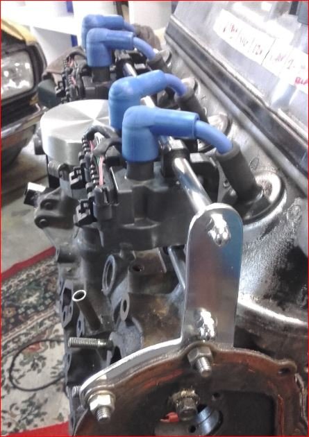
Yeh, Taz did something similar, but instead of using COPs, he mounted quad coils on the side of the engine. Real nice neat setup ! I believe the Nissan CAS is under that spun aluminium lid on the dizzy. Cheers Banjo
-
Hi Dave, Been there done that ! Played with wasted spark, & have had it running successfully. It is certainly the simplest arrangement to set up ! No distributor; No synch signal required; No toothed gearwheel; Simple crankshaft triggering only; Only 2 off coil ignitors required. Only downside is, that you need more expensive platinum spark plugs, as the spark jumps across the gap, in two of the plugs in the wrong direction, & quickly eats away the outer electrode, if normal spark plugs are used. Nothing against waste spark. The system pictured above, worked perfectly ! Those two (2) coils are ex Commodore. The coil mounting base-plate is Commodore also, gutted & a couple of DIY AutoTune Bosch BIP317 ignitor ICs fitted, the base plate becoming the heatsink. Crankshaft trigger is two (2) rare earth magnets glued into two existing manufacturing "jig" holes in the flywheel ( 180 deg apart), which are picked up by a Hall Effect sensor, mounted & accessible on the engine backing plate, directly underneath the coils in the above picture. This is a mod, almost anyone on this forum, could accomplish at low cost, with noticeable improvements, even to a stock engine. The need to fire the plugs sequentially, is a result of now wanting to use the COP conversion I have carried out on a K Series head. The EFI system, I also want to work sequentially, so will have four (4) outputs for COPs, & four (4) outputs for injectors. I will then be able to compare both systems, possibly on the same engine, as swapping over to "waste spark", from "sequential", is easy. Cheers Banjo

-
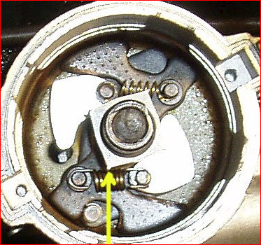
Any olde points Corolla dizzy can easily be turned into a synch signal, without much toil. At the moment, the points open & close 4 times per revolution. If you ground off three of the four lobes, it will open & close once per revolution. You just then turn the dizzy around until the points open say 50-70 deg BTDC No: 1. Alternatively, if you want to go electronic, put in an Accuspark module, & grind off 3 of the 4 imbedded magnets, in the piece that normally is fitted under the rotor. Accutally, if you used the electronic dizzy as you have pictured above . . . . It would be so much easier than a points one, as you just grind off three of those "tips", you have highlighted, and don't have to worry about rounding it off, as you would do with the points type, as the rubbing block, still has to be in contact with the shaft. Cheers Banjo
-
Hi Viterbo, Thanks for the tip on the Speedinuo ! I did not realise that someone had done all that hard code work, & put it into a package. Had a quick read this morning in bed, & it looks good, & well thought out. Could be a very competitive product to the Megasquirt, as it appears to be more compact. The only question I found while reseaching, is that the "timing accuracy" leaves a little bit to be desired. However, firmware is always being updated, so I'm sure that will be resolved in the future, as long as the Ardinuo micro is fast enough. Bear in mind, the errors I saw they were quoting, were at revs of 13K rpm, which few on here with K series motors will ever get to half that. The oil pump shaft is really simple. Just get an olde dizzy, & hacksaw the top off. A number of people on Rollaclub, have done this. It just needs a lid on the top, to cover the end of the shaft. Someone on here, used a whelsh plug, pressed onto the remaining bottom of the dizzy, turned down to suit. Looked good. That's what I intend to do. You could create a a trigger, synch, or sequential signal for an electronic ignition system, using a optical wheel. I did that in a Rolla Bosch dizzy, with shaft locked up & everything removed. If it is used simply as a synch signal, to tell the ECU, that the next crankshaft trigger signal should be directed to cylinder No: 1, then a bit of slop in the camshaft chain & sprockets etc. is not an issue. However, I was using it a trigger signal, & the strobed timing mark on the crankshaft pulley, indicated it wobbling around 2-3 deg. It was at that time, that I decided crankshaft triggering was the only way to go. Once I triggered off the crankshaft, the strobe was rock solid, which proved the timing chain & sprockets were the culprit, & I would never return to camshaft triggering again. Cheers Banjo



-
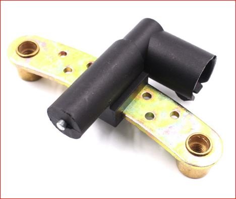
Hi Pete, Thanks for that. Is this picture the same as the sensor on your Renault ? This particular picture is an aftermarket one, but the same structure. These are relatively cheap, & I can get one for less that $ 20.00. However, I don't believe it is a Hall Effect type, as it only has two wires, according to the pics I have found of it on the net. There was an issue with them, & Renault did make a change, as you suggested, but it was to do with the electrical connection, that vibrated, & went o/c occasionaly. http://www.partinfo.co.uk/files/Cambiare Tips and Tricks Issue 11 PDF.pdf http://garagewire.co.uk/news/company/fps/problem-job-renault-crankshaft-sensors/ There are numerous complaints on the net of them attracting magnetic rubbish, as there is a magnet inside them. You simply take them out, clean them, & put them back. Actually, your suggested sensor is exactly the right shape & size, to easily be adapted to the K50 bellhousing. It would probably require some conditioning amplifier, to square up the sinusoidal waveform, that these "inductive" sensors produce. I'll get one & have a play. Even if it is not electrically suitable, the case may be very useful. Cheers Banjo
-
Hi Dave, Thanks ! I'm having fun. I'm very happy with the programmability of the Jaycar ignition system. It was one of Silicon Chips most successful automotive projects. The kit was recently discontinued, in December last year, & I snapped up a few kits that were left in one store. I recently even sold one to a fellow Rollcluber in Portugal. The Silicon Chip project was never intended for a distributorless application. It had one output, that triggered an ignitor, which fired a single coil, whose HT output was fed to the centre tower of a conventional dissy cap, to be "distributed to the four spark plugs, as normal. All I am going to do is create an electron "dizzy cap", so to speak, that will direct the o/p signal to the four ignitors built into the COPs. That's the easy bit. I'll use either a small Picaxe, or an Arduino uP. Just got to sort out this ring gear pickup sensor, as the integrity of that signal, is crucial to the whole system working flawlessly. I do have a back-up plan "B" if I'm not totally happy with the ring gear sensing precision, or reliability. I could drill eight (8) radial holes in the flywheel, & fit some cylindrical rare earth magnets, alternating North & South poles, facing out. A bipolar Hall Effect sensor would pick up the south poles & turn on, & then turn off, when the north pole presented itself. The magnets could be positioned so the period in which a particular spark plug was fired, would only be an angle, through which normal advance & retard normally operates over. (eg: 50 deg BTDC to say 10 deg ADTC. This would reduce considerably the possiblity of cross firing. However, the ring gear proposal, is the simplest, & easiest. Because it is counting the teeth, which are 3.4 deg apart, (360/106 teeth) I could set the this "firing arc", to be anything I wanted, within 3.4 deg accuracy, which is not important. To do that with magnets, you have to redrill flywheel & reposition, if required. The Megasquirt alternative I still have noted for my 4K EFI conversion, which is sitting on my test bed, awaiting some finishing touches. This project is an inbetween one, which can very easily be introduced to my road car now, to see how it works in the real world. I wanted to make the mods for triggering & synching simple, that didn't require major changes to the engine, itself, for interested parties. When I get to the Megasquirt, I'll definitely give you a yell, as I'm never interested in reinventing the wheel, if someone has been there before. Cheers Banjo
-
Hi Guys & Gals I am in the process of building an electronic ignition system on a 5K engine, I have here on a portable engine stand. The electronic ignition has been working perfectly in my daily drive KE30, without a hitch, for sometime. It uses a "locked up" 3K dizzy, with an Accuspark module in it, used purely as a triggering source. It uses the Jaycar programmable system, to provide a customised advance & load retard map. The next stage is to go distributorless, altogether, using the COP conversion I have carried out to the K series head. I am going to go full sequential firing (1,4,3,2) rather than waste spark, but it is easy to try, or revert back to "Waste Spark", once you've gone sequential. I'm considering how to provide the crankshaft position sensing information. There are plenty of aftermarket systems, I could bolt onto the front of the engine & crankshaft pulley. However, these are fairly expensive, & prone to get damaged, or misaligned, at that position on the engine. The area I am looking at is the flywheel ring gear as a source of pulses. Bit like a Nissan “optical dizzy”, but signal sourced from the flywheel ring gear. . The K Series flywheel has 106 teeth on the ring gear, which makes 212 teeth per 720 deg of rotation, which is a full 4 stroke cycle. That number, results in a full number, when divided by 4 cylinders (53) The ring gear already exists, so it just needs a sensor. I’ve cut a little hole in the bell housing to get easy access to the ring gear. A synch sensor can easily be derived off the large timing chain sprocket, which I already proved, & works well. I may even look at using the fuel pump lobe on the camshalf, if I fit an electric fuel pump down in the boot. Some manufacturers apparently used flywheel ring gear sensing in their earlier attempts. Research shows some European models went this way. Early attempts used inductive 2 wire sensors, but most later model cars, used Hall Effect sensing 3 wire sensors, as the Hall Effect sensor has constant amplitude, irrespective of the revs. The commercial automotive Hall Effect sensors are pretty expensive, so if I buy one, I want to be pretty sure it will work on the K series ring gear. I have just spent some time building a Hall Effect sensor using the model UNG3503 Hall Effect component, & mounting it with a small bias magnet, behind it, in a small aluminium tube. It took a bit of experiment to get the bias magnet positioned correctly, so that it wouldn’t switch until the ring gear tooth was in line. However, when I rotated the flywheel, the sensor would not turn off, due the magnetic hysteresis of the sensor itself. Probably due to the width & depth between teeth on the flywheel. I’ve decided to give that away, & just get a commercial Hall Effect one, that I know will work, because it has been used with ring gear, in its original application. Has anyone on here any advice, or experience, as to which crankshaft position sensors, available as a spare part . . . . , were 1. Hall Effect (3 wire), & 2. Intended for, & used on flywheel ring gear ? Cheers Banjo


-
Hi Graeme, Picture No: 1 of the Gumtree ad, indicates the car has no windscreen ! How much more air conditioning than that, do you require ? Cheers Banjo
-
Hi Bruce, No, I never wanted to lower it too much, as it limits me where I can go. I have some Old Skool Delta 14" mags on her, & they just (I mean just) clear the large Cressida rotors & calipers I have fitted. However, the standard KE70 King Springs I fitted, were made from King Springs newer material, which results in a much stiffer spring. When I first dropped her to the ground, she sat up in the front. I drove it around for a month or so, thinking the springs might "settle", but no such luck. I finished up taking about a full coil turn from them, to get the ride height to match the rear. Perfect now ! It gives a firm ride in the front, assisted by the 22mm dia. sway bar. Bit harsh on rougher roads, but corners, like it is on rails ! The full coil turn removal, still kept the coil spring captive, with air under the wheel. From all I've learn't whilst doing my front end, I'd like to have another go at it, with a different approach. I've always believed that there is something basically wrong with the whole McPherson strut design/geometery, if it is not just right. There appears to be a lot of "chat" on the net to support that. When I was young, I owned a "Harry Potter" Ford 105 Anglia, which I drove all over Australia, when I just got a licence. It had an inherent issue, where the front end would get a violent "shimmy" up, at a particular/exact speed. No end of balancing & wheel alignment could ever fix it. I just used to drive through that speed range quickly. I'll take some pics of the ride height later today, to show you what I finished up with, & add them here. Cheers Banjo
-
Nope ! There are still cheap AE86s around. Here's one currently up a Gumtree. Cheap, & keep you busy for a few weekends ! https://www.gumtree.com.au/s-ad/glenmore-park/cars-vans-utes/1985-toyota-sprinter/1189229501?utm_source=criteo&utm_medium=cpc&utm_campaign=MF-cars-MAU&utm_content=120777_9299 Cheers Banjo
-
Hi Stuart, I was very lucky ! My wife's very first car was a KE30. When I married her I inherited a/her Celica RA40, which we cruised all over Australia, until kids came along. She currently has a late model Corolla, but strangely enough, when she goes shopping at the weekend, it's my KE30 that disappears from the driveway, for an hour or so. P.S. I keep telling, to check I'm not under it, when she hops in it. (We have four Toyotas in our family) Cheers Banjo
-
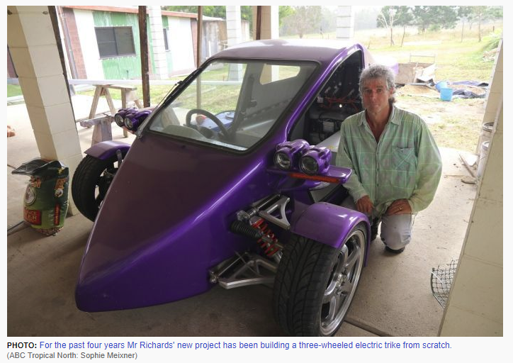
Maybe an early electric car ! This picture was part of a story on electric motor conversions on older & classic cars, on the ABC website today. http://www.abc.net.au/news/2018-07-24/make-your-own-electric-car/9918964 Does anyone know of a K Series Rolla anywhere that has had an electric motor substituted in place of it's 3K/4K unit ? Cheers Banjo
-
Hi Graeme, Here is another one around that pricing area. https://www.gumtree.com.au/s-ad/adelaide-cbd/cars-vans-utes/1987-ae86-levin-coupe/1189715163 Cheers Banjo
-
Life is full of What Ifs !


