Leaderboard


Popular Content
Showing content with the highest reputation since 07/20/25 in all areas
-
That is a strange one. Have you upgraded your headlights or the bulbs recently ! There is no headlight relay in the early Corollas. The headlight current passes through the contacts in the headlight switch on the column. I can only suggest that when the headlights are switched on, the +12V to the dash assembly drops off somewhat. The fuel guage is fed by a regulated voltage less than 12V, so that the guage always reads correctly. Are the headlights a bit dull also. I would measure the +12V at the steering column, with the headlights on & off, & see what the difference is. The regulator for the fuel guage can use a 7, 8, or even 10 volt regulator If the head lights are dropping the +12V supply to the dash, to less than 10 volts, that may be what is causing it.. My suggestion; is to have the headlight switch control an automotive relay only. Use the relay's contact to switch the +12V directly from the battery, via a 15A automotive fuse; to the headlights. P.S. Have a read of recent thread, which may help you shed some light on the issue. https://www.rollaclub.com/board/topic/85671-ke55-cluster-not-working-properly/#comment-738595 Cheers Banjo1 point
-
It appears to me; from your photos, that it may be, that the ignition switch itself is OK, but the plug in connector & socket that connects the ignition switch to the car's wiring harness, is corroded & unserviceable. I may well be, that if you cut off the plug & socket, & substituted another generic plug & socket; or simply connected/soldered the wires together, without the plugs & sockets; then maybe the car will work perfectly. As You have the ignition switch out; You could test that the contacts inside the ignition switch connect OK, with a simple multimeter, or a battery & test light. Even if that is a temporary measure, to get you going again; it would then allow You time to search UK, French & German ebay sites, & see if anything comes up when looking for Neiman ignition barrels. Even if You can't connect it up, without the plugs & sockets; then any good auto electrician, should be able to do that for you, & get You mobile. Cheers Banjo1 point
-
Do you think that was a factory part when the car was new? ..or has someone fitted a European ignition system to it afterwards? If you're lucky its a common Neiman part shared with other cars in the 80s, so you could get a second-hand one in good condition, or a new one from another one-make car club. There are Ferrari ones for sale... Do you know what America used? The column should be the same as yours. Which part do you desperately need, and can you substitute wiring and contacts from generic electrical parts? How's your French? https://mtparts.fr/product-categorie/japanse-tractor-parts/suzue/electrical-parts-suzue/1 point
-
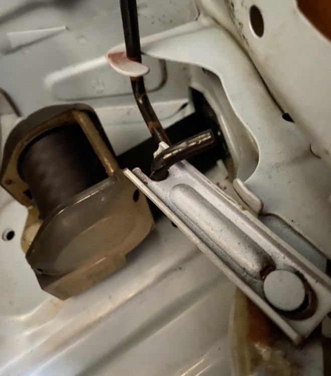
The plates are 80mm long x 23mmwide, neatly pressed from a flat maybe 30mm wide to roll the edges for strength. Open slot one end, closed slot on the pin end. Not an easy shape to make.1 point
-
The usual torsion bar spring used in the 70s.. and the other side... They can be quite grunty springs when you try and fit them!
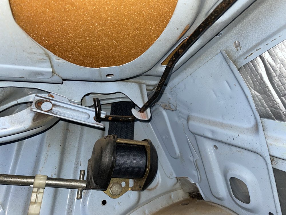
 1 point
 -
Hi Alasdair ! Thanks so much for that wonderful set of photos. Only one sentence describes this . . . . "A work of Art & Dedication". Well done ! What colour have you decided upon, for outside. Matching the engine bay ? I take my hat off to You. Accomplishing body work, is not a great joyous part of working on any car; for me; so I really applaud your dedication. Now the fun part comes for me. The putting it all back together, & hearing that first roar to life, as You turn the key for the first time. Keep the photos coming. You provide inspiration to others. Cheers Banjo1 point
-
"Witnesses told Hawke’s Bay Today they saw the men inside the jewellers smashing cabinets and taking items." When I was young that jeweller would have whipped a shotgun or a revolver from under the counter and sorted those clowns out!1 point
-
T-series yes,stock Borgie...meh! Of course any diff you buy is 40years old and probably needs rebuilding anyway. I had my T-series done earlier this year, but I can still hear a slight whine from it, everything else is worn as well as the bearings. Make sure you have the bearings in your hands before pulling the diff out if you need the car.1 point
-
Hey guys Just wondering if there’s a difference between ke20 lower control arms and te27 lower control arms? wanting to run the te27 gtx2 T3 lca and caster arm kit on my ke20 cheers
 1 point


