

Banjo
Regular Member
-
Joined
-
Last visited
Everything posted by Banjo
-
One of the problems with trigger wheels, is the need for specialised equipment, to check that the multiple critical timing signals, from the crank & camshaft position sensors, are working properly. There was something to be said for the simplicity of the “Kettering System”; we are used to; where if your engine did not fire, you quickly removed the dizzy cap, & could quickly decide what was the culprit; sometimes just visually, or with a simple screwdrive & trouble light. With the trigger wheel in particular, this becomes even more critical, once you understand how the ECU interprets the signals coming from the VR or Hall Effect Sensor. eg: If the air gap of the sensor from the trigger wheel teeth, was a little wide on just one or two teeth, such that a signal was not produced from those particular teeth; then those missing pulses, to the ECU; could well appear as if they were the intentional missing teeth on the trigger wheel, & throw the complete timing out. Take the case of say a destroyed/missing magnet, due to being dislodged by the centrifugal forces on it. Same result; the timing gets thrown out completely. I decided that I would build a simple opto-coupler & LED visual system, that allowed very simple & quick, verification, that the signals from both crank & cam sensors were working correctly, while cranking the engine. The results were a simple small “black box”, housing the electronics, with two (2) visible LEDs, that was mounted near the front of the engine. Placed there, it could be viewed, if for instance, you were turning over the engine by hand, very slowly; to check whether every tooth, or magnet, in the trigger wheel, was creating a pulse. I posted a picture of this little box, earlier in this thread. However, there was an issue. When the engine was being cranked, with 35 magnets (36 – 1) producing 35 pulses every revolution, visually; you cannot see the clear make & break of each trigger wheel transition, & the LED looks like a blur, for the crankshaft LED pulses. So I decided that if I built a counter, that counted the individual teeth/magnet signals, & only produced a LED pulse once the count was reached; say once per rev; it would clearly indicate that all was good. I would still retain the LED that indicated every tooth or magnet transition, so that you could turn the crankshaft over with a ratchet & socket, & see every individual tooth pulse, if needed. The result was even better than I envisaged. The counter I used had an output for a count of 32, which was close enough to one revolution of the trigger wheel/disk. I could have made it count exactly to 35, or 36; but that would have required an extra IC chip, & the result would not be noticeable. Cranking the engine with the spark plugs removed; which is the fastest cranking speed possible, gave a clear visual indication of the cam, crankshaft pulses, plus a clear LED pulse output for approximately every revolution of the crankshaft. The resulting box is shown below. I’ll drawn the circuit up, & post it on here, with a description of its operation; in case there is someone on here that wants to replicate it. Cheers Banjo


-
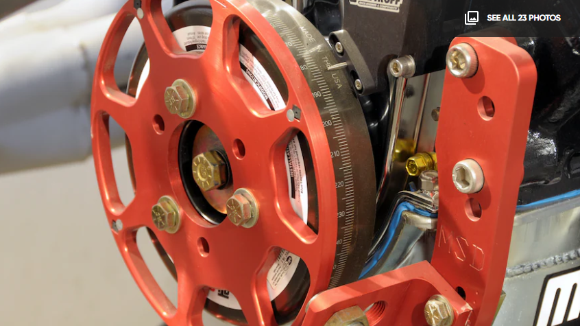
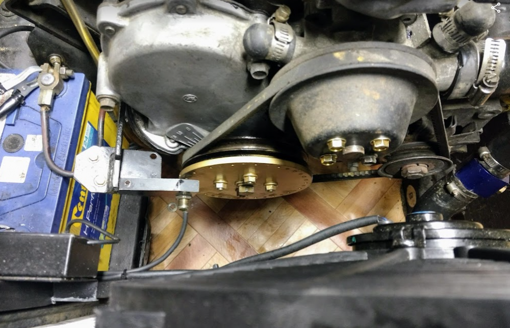
I read a couple of stories on the web, regarding some people poorly fitting trigger wheels to engines, where the results have been catastrophic. It led me to research the use of a harmonic balancers, in general, & on K series engines. https://en.wikipedia.org/wiki/Harmonic_damper Torsional twisting, flexing, & vibration are typically more common in long crankshafts, such as are found in straight six & eight cylinder engines. It occurred to me, that our little K series engine did not fall into that category, so why did Toyota feel the need to fit a harmonic balancer. The K series engine, also has a main bearing on the crankshaft between each & every cylinder, so should theoretically, be pretty safe. Bearing in mind that 1200cc K Series engines, were successfully used in midget dirt track racing cars in previous decades, at rev limits at least twice what they were designed, would I have thought; proven them almost unbreakable. In fact, I believed the only K Series engine that was fitted with a harmonic balancer, was the 5K; however, I have since discovered that there were some 4K engines that came out with harmonic balancers fitted, & I presume the 7K had them also. Even the very simple & small crankshaft pulley fitted on the 3K engine, were balanced at the factory, as the few I have on the shelf here, all have 1, 2, or 3 balancing drillings on the rear of the pulley. The crankshaft pulleys on the 3K & 4K, were also quite small in diameter, compared to the much larger diameter, fitted to the 5K. When fitting a trigger wheel, to the crankshaft pully, the bigger the diameter, & the more trigger teeth; & the faster the ECU can respond to crankshaft rotational speed changes. The problem appears to be, that the trigger wheels themselves are not balanced, & in many cases, the reason the trigger wheel, failed; was because it was attached; (even welded), to the outer harmonic balancer pulley itself. It was for this exact reason, that I made my trigger wheel 150mm in diameter, which is only a little bigger in diameter, than the 5K pulley outer diameter. That also accommodated a 36-1 configuration, & still left sufficient distance between the rare earth magnets, to obtain very clear switching transitions, which I have checked on my oscilloscope. It is also, one of the reasons, why I made my trigger when out of aluminium, rather than steel. I have a similar sized steel trigger wheel, which I bought on line, & it weighs 550gm (over half a kilo). By comparison, the aluminium trigger wheel, also 6mm thick, like the steel one; weighs just 200 gm. The other issue that makes the steel trigger wheel an issue, is that the majority of trigger wheels have either one or two missing teeth, at one position. The lack of two teeth; naturally create an imbalance, but most trigger wheel manufacturers, simply drill a hole in the trigger wheel, close to the outside; exactly opposite the missing tooth/teeth, to compensate. Because my aluminium trigger disk, does not use teeth at all, the only imbalance would be one 4mm x 5mm rare earth magnet, whose weight is tiny. I can easily drill, at 180 deg., to compensate, for the missing magnet, or just not drill out one hole. I also took care, in ensuring that the trigger wheel/disk, was only attached physically, to the crankshaft pulley “centre piece"; & spaced off the centre piece, so it cleared the pulley grove section of the harmonic balancer. The real beauty of using aluminium wheel, & the tiny rare earth magnets, is that you aren’t confined to using the traditional VR (variable reluctance) sensors, whose output signal needs conditioning; before it can be used reliably, by the ECU. The only disadvantage I can envisage using magnets; is that they may attract, iron filings, to attach to the disk. Might be an issue, if you plan on driving your Rolla around the Pilbara area of W.A., but should not be an issue on sealed roads. The worst case scenario, would probably require a little fixed brush in place to keep the face of the trigger wheel free of debris. Cheers Banjo



-
Received an email from T3 this morning, including a gallery of pics they took at the above event. For those of you, who love looking at restored classic Toyotas; where attention to detail, & money has no limits, you will enjoy scrolling through these pics on the T3 FaceBook site. https://www.facebook.com/media/set/?set=a.5630226273683848&type=3 Enjoy ! Cheers Banjo
-
Good news indeed, Luca ! Always a sinking feeling, when you have spent precious bread; on something, like an engine; & then face the thought, you might have bought a lemon. All good from here on in. Keep us in the loop. P.S. where are you located geographically ? Cheers Banjo
-
That's why the distributor is so importantant to the operation of the oil lubrication system. No distributor; then the oil pump cannot be turned. In motors where I have done away with the distributor altogether, I have used a cut down dissy base, with a cap, purely to drive the oil pump. Hope you have some good news to tell us tomorrow. Cheers Banjo
-
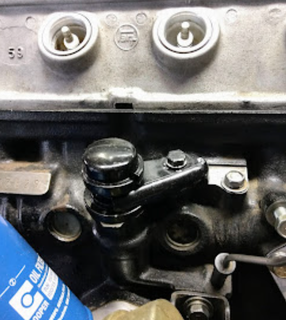
Hui Luca, Here is a pic that clearly shows the oil pressure to the head, passing through the camshaft bearing journal once every two rotations, of the crankshaft. Hope that solves your problem. Just hook up a battery, & turn over the engine. If that is not possible, then drive the oil pump, via your drill & screwdriver blade, & get a second person to slowly turn over the engine with a 17mm ring spanner on the crankshaft pulley centre bolt, until the camshaft holes line up, & you hopefully will witness oil squirting out of the hole you circled, on the block. P.S. Don't forget to put the dizzy back in, if you are using the starter motor to turn it over, as it needs that, for the oil pump to turn. Let us know how you go. Cheers Banjo

-
Hi Luca, I'll pull out the "yellow Bible", on the K Series engine, & see if I can't scan the relevant part about the lubrication system. I keep forgetting you are not turning the engine over with the starter motor. Is that not possible. I note it is connected, in your pic, on this thread. Cheers Banjo
-
Your issues, triggered a memory of such an issue I had with a K Series engine years ago. You might like to read this thread, where others pitched in with ideas. https://www.rollaclub.com/board/topic/5130-oil-pressure-problems/#comments The Ryco site doesn't list the Z386 oil filter as being suitable for the K Series engine. Cheers Banjo

-
So if there is no oil coming out that circled hole to the second rocker shaft mount, from the front, you can be quite sure, that the issue is in the bottom half of the engine. I just looked up a Z386 Ryco, which is one I have on the shelf here, for a later model Toyota Corolla or Echo, my daughter or wife has. The Ryco one specified for the 5K, as well as other K Series engines is the Z68. I tend to use the Z423, which has an anti drain back valve, which the Z68 doesn't have, off memory. the Z423 is also used by some Merc models. The Z386 is quite a small filter physically, by comparison, to the original Z68, specified for the 5K engine. Have you got a picture of the Z386 filter mounted on the block ? It has a pressure relief valve & an anti drain back valve built in, but not an anti syphon valve. I'm now wondering wether there is someting wrong in the filter department, that is draining the oil straight back into the sump. The only other place, short of leaving a bearing slipper out, during reassembly, would be something to do with the timing chain tensioner, or oil squirter, for the chain. We are fast running out of alternatives, to dropping the sump, as I believe the engine, is already in the car. Cheers Banjo

-
Hi Luca, What is the brand & model number of the oil filter on your 5K engine ? I'm presuming it was brand new, when it was fitted to this engine, that has never run. It just sounds to me, like you might have an oil filter with a faulty high pressure valve, or the like. If in any doubt, then simply replace the filter with a brand new one, & see if that changes the results, you are currently getting. It's an initial cheaper option than getting the sump off. P.S. Does this 5K block have hydraulic or solid lifters. 5K blacks were manufactured with both configurations. Was the 5K convertered to solid lifters, at some time ? P.S.S. Did the rocker shaft supports have any shims under them, between base & the head ? Have heard of oil pressure issues, sometimes, if a solid lifter conversion, is not carried out properly. Cheers Banjo
-
Hmmm ! So if the engine has a higher compression, did the "engine builder" use a special head gasket, or a standard one. Off memory, there is only one oil feed to the rocker gear, in one of the central rocker supports. Not sure whether all rocker supports are the same, or if you got them mixed up, when reassembling, it could be possible to block the oil feed. I'll have a look at a set of rockers, when next I head to the shed. Cheers Banjo
-
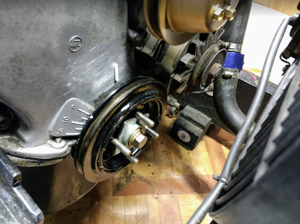
The next job, was to confirm TDC No: 1 & 4 cylinder’s markings on the engine, as this is critical, for setting up all the other; cam position sensing; & missing tooth positioning, on the trigger wheel. This does not involve having to watch the no: 1 cylinder inlet valve, through the oil filler hole. It does however, require the removal of no: 1 or no: 4 spark plug, to be able to see when the piston arrives at the top of its travel. In fact it is much better, to carry this out, with all four (4) spark plugs removed, as there is no compression to work against at all, when rotating the engine by hand. Anyone who has ever looked down the spark plug hole, & tried to visually pick the exact top of the pistons travel, will know, that it is not that easy. For several degrees before & after TDC; the piston; visually, does not appear to move, at all. I’ve always used a different technique, widely suggested by mechanics on the net. It involves a TDC “stopper”, being screwed into the spark plug hole, & it’s length adjusted, so that the piston travel, is stopped before it arrives at TDC. I know you can buy a professional tool that does this, (see above) but I built a similar device, years ago; using a gutted old spark plug, & a long threaded bolt, with a lock nut. It looks like this. The technique, is to rotate the engine until it is about 5-8 deg BTDC. Then adjust the “piston stopper”, & screw it into the spark plug hole, until it just touches the top of the piston. 1. Rotate the engine by hand anti-clockwise (from the front of the engine), then ensure the piston stopper is firmly screwed into the head. 2. Now, rotate the engine clockwise, until the piston can’t travel any further. This should be carried out carefully, & gently, as you don’t need, or want have the piston stopper in any way; damage the piston head. Now turn your attention to the front of the engine, & place a mark on the timing chain cover, directly behind the “nick” in the crankshaft pulley edge. White-out, is your best friend for this job. 3. Now rotate the crankshaft, anti-clockwise, until the piston again touches the “piston stopper”, but this time, from the opposite direction. Repeat the previous in 2. above, & place a mark on the timing chain cover, directly behind the “nick” in the crankshaft pulley edge. 4. If you done this correctly, you should finish up with two adjacent marks on the timing chain cover, that are say 5-10 degrees apart. 5. T.D.C. is a mark you will add that is exactly half way between these two marks you previously marked. However, in my case, the TDC marks on the timing chain cover, were no where near, where Toyota had designed them to be. I went & pulled an old timing chain cover from the heap of Rolla stuff, I have in my shed, & indeed, the timing marks on the timing chain cover, were more to towards the centre of the cover; instead on the far left hand edge. One thing that is I believe common, with all K Series engines; is that, at TDC 1 & 4; the keyway on the crankshaft, is always vertical, & at the top. I then went & got a 4K crankshaft pulley, & with keyways lined up, the timing marks were in different places. So what had happened here, was that I had removed the original 4K crankshaft pulley, & replaced it with a 5K one, which is larger, & has a rubber harmonic balancer built into it. There are a couple of different 5K pulleys, as some had extra belt grooves, for driving hydraulic pumps & the like, on forklifts & the likes. So the answer to my problem was simple. Either, fit a 5K timing cover to the 4K engine (not going there today thank you) Use the 5K pulley, but simply move the timing mark on the pulley lip, so it lines up, with the TDC mark on the 4K timing chain cover. So, I marked the spot on the 5K pulley that lined up with my centre mark on the timing cover (see pic above); then removed the pulley; cut a new timing mark on the rim; a quick black spray of the pulley then placed it back on the engine. I had used the 5K pulley for two reasons. It had four (4) existing threaded holes, that were perfect for securing a trigger wheel, that was bigger than the pully. No doubt, it could be done with the smaller 3K/4K pullies, & I’ll look into that when next I build another trigger wheel. So why did Toyota, move the timing marks on the timing chain cover, to the centre, from where they had been on the earlier 3K & 4K engines. Someone on here might know the true answer; but my guess is; that in 5K, & presumably 7K applications also; other ancillary equipment, belt driven by the crankshaft pulley, may have obscured the timing marks, on the far LHS. So once all that was sorted, all that was left to do, was fit the degree disk to the flywheel, with some double sided tape, & ensure the pointer lined up, with the TDC markings on the degree disk. Cheers Banjo


-
Hi Luca, That last picture of the head & rocker gear, indicates that the gear has been unlubricated for a while. As you are getting oil at the dizzy meshing point, which is normal, as oil is drawn up the dizzy shaft with oilways in the shaft, to the dizzy bearing. Most Denso dizzies have a hole in the base to drain out any excess oil that gets to the dizzy bearing. It looks like there maybe a blocking of the oilways to the head; with the head gasket used, or the head & block oil ways may not line up. Before ripping the head off, I would simply unbolt & remove the rocker gear, & see if any oil comes up the oilway, when you rotate the oil pump, with your drill. How long have you been running this 5K engine, block with a 4K head ? If this suggested test, doesn't produce a clear answer; & the rocker gear removed, hasn't been oiled for a while; you may well have to then remove the head. Good luck, & keep us informed. Cheers Banjo
-
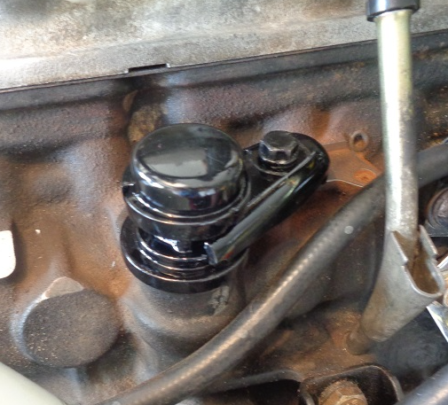
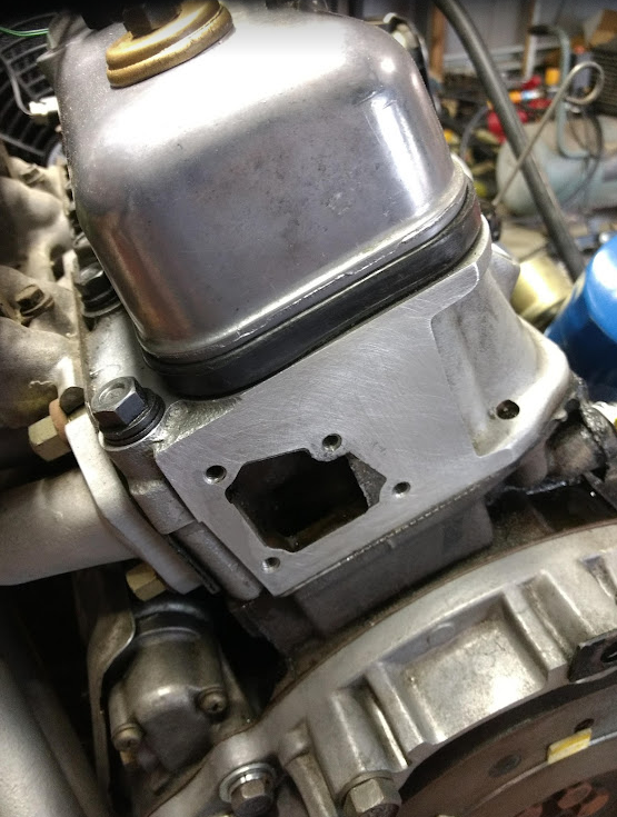
So with an EFI setup, we no longer need the mechanical fuel pump, on the engine. You could simply remove it altogether, & replace with a hand crafted cover plate. I've never come across a cover/blanking plate, specifically made for the K series engine. However, the hold down bolt spacing, is almost identical to some Ford 302 V8 engines. I came across such an item, chrome plated, on ebay, & it fitted perfectly. When it arrived, I was surprised how thick & solid the plate was. The idea occurred to me, that this would be a perfect place to fit an intake for the crankcase ventilation on the K Series engine. Existing crankcase ventilation is pretty basic & elementary, & not very effective. All I needed was a neat little filter to attach to this plate. I've used them before, as have others on here, & attached them to the top of the rocker cover. However, the attachment point, & passage for the air to pass through, is only about 12-15mm, in diameter. If only I could get one with an opening nearly twice that size. Again, ebay to the rescue, & I found just such a filter, with a 25mm diameter round opening. So drill a hole in the blanking plate, half way between the hold down bolt holes; open it up, & weld or braze a 25mm a spigott to take the filter. I found an old brass tap fitting, in my box of junk, that was perfect. So this is what it looks like, back on the engine. Cheers Banjo


-
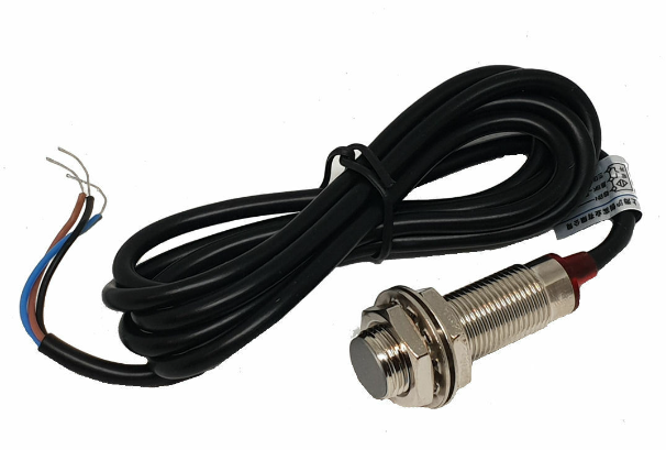
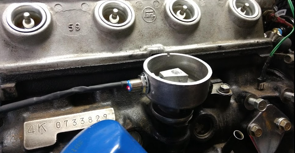
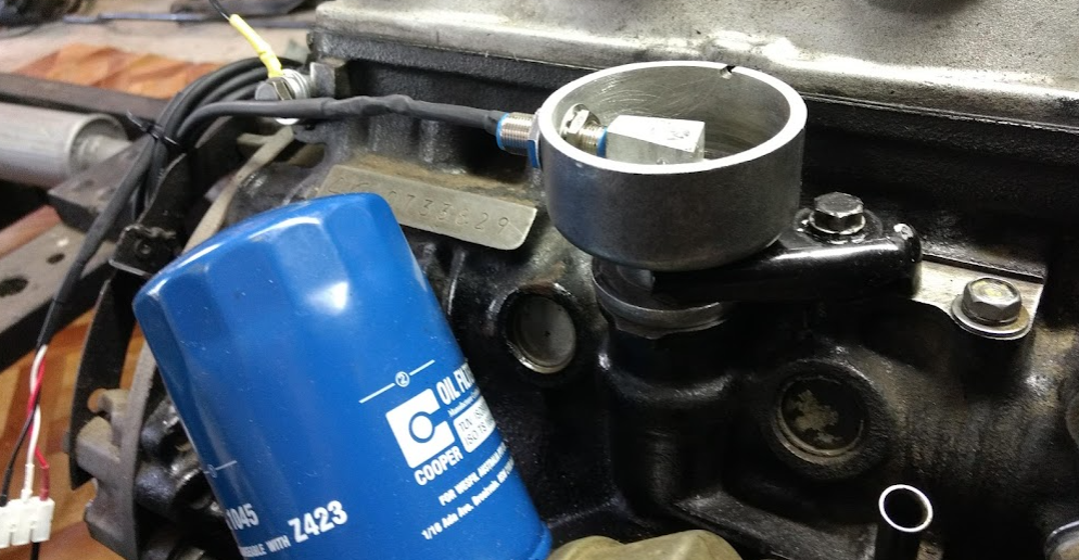
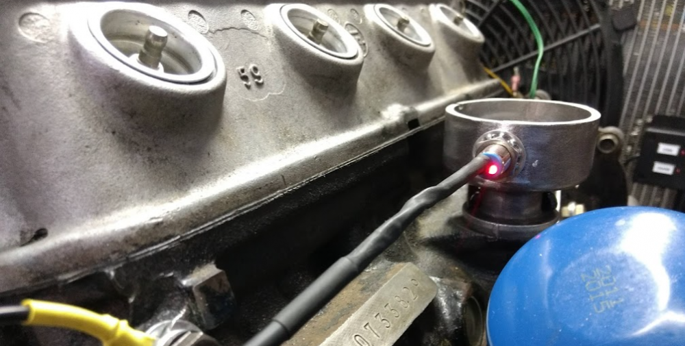
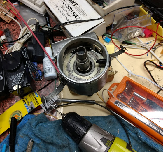
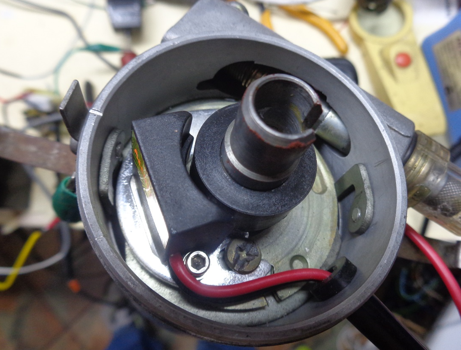
So got a few things done on the engine over the weekend. The weather in Brisbane was a warm 25-26 degs both days, so it was pleasant to be in "the shed". I fitted the original dizzy cap spring clips, to the cut down cam position sensor. They were obviously too long, as I had cut the main body down; however, when I mounted the " connecting lugs, on the underside of the dizzy body, instead of the side; they worked perfectly. Anyone, can make one of these up, with basic tools & a vice. The Hall Effect sensor I used is a common one found on ebay, & readily available for about $ 10.00. It is threaded, which means positioning is easy, & it has an LED built in at the rear, so that operation is easily confirmed, without taking the "jam jar" lid off. It's part number is NJK-5002. NJK-5002C It is defined as a proximity switch, & has a very small magnet, secreted internally, behind the Hall Effect device. When a "ferrous" object passes the face, it switches on. However, if you use a small magnet, instead of ferrous metal, on the "trigger wheel", the field is much much stronger, & the gap between the magnet in the trigger wheel, & the defecting face of the Hall Effect sensor, is almost irrelevant. I've had it working with a gap un to nearly 10mm. Cheers Banjo


-
Yep ! That works. I've tried it once or twice in my "Corolla life". Get an olde blade screwdriver with a reasonably long shaft. Cut off the handle, & attach to an electric drill. Make sure the drill is speed controlled, as if you use the drill at high speed, you will either have oil all over the place, or you could do yourself damage, if the blade comes out of the oil pump slot. Remove the oil pressure sensor, just below the oil filter. Beats removing the sump & oil pump, to test. Rarely do oil pumps completely fail, but the high pressure bypass vavle in the oil pump body, have been known to stick open if something tiny gets jammed in there. Happened to me once in a Fiat 125S, but that's a long story; & a long time ago. Cheers Banjo
-
Interesting read, on this subject today, with some amazing statistics. https://www.abc.net.au/news/science/2022-09-03/electric-vehicle-what-it-is-like-driving-across-australia/101390376 Cheers Banjo
-
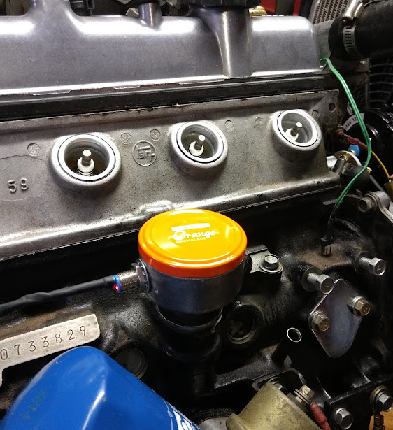
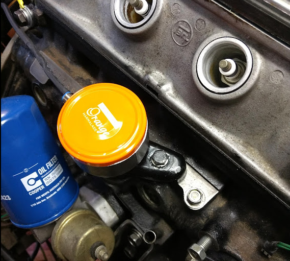
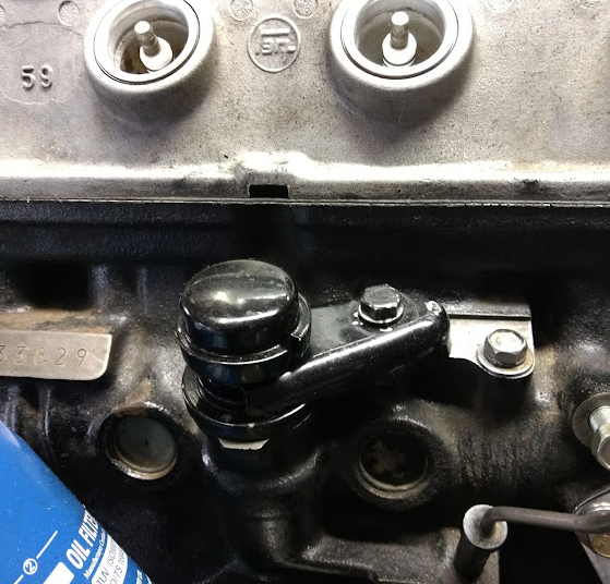
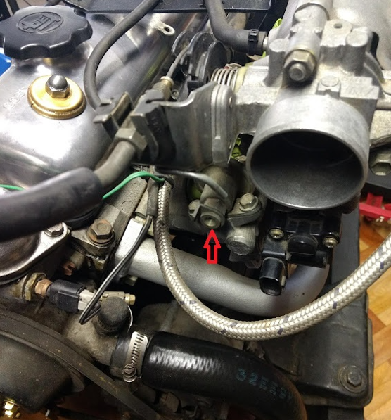
Got hold of a couple of metres of 5/6" (8mm) Hi pressure fuel hose, to use to direct coolant to & from the IAC Valve, tucked under the throttle body. I made sure that the hose connection points on the rear of the head, & the inlet of the water pump, were the same diameter, as the hose connection points on the IAC valve. No in-line hose size adaptors required. It is important that there is a means to be able to check the cam & crank position sensors are working perfectly. One of the nice things about the Hall Effect sensors I am using; is that they have a little red LED incorporated at the rear of them, which blinks clearly, as you crank the engine. The cam position sensor is easily viewed pulsing, as at cranking speed, as it turns on, just once for every 2 turns of the crankshaft. However, with the crankshaft trigger disk, with 20 odd magnets around the circumference; even at cranking speed, the flashing of the LED, becomes a blur, as the time the LED is off, is so small. I am building a counter, so that the LED will flash, each time the count get to a number that is closer matched to the flash rate of the cam positioning sensor. I've built a little box, with the Crank & Cam position LEDs, therein, which will include the counter, & allows you to view both crank & cam position sensor LEDs, at the same time. I've also added a couple of opto couplers in there, so the crank & cam position sensors, are electrically isolated from the ECU completely, to reduce any electrical interference in the engine area, effecting the ECU inputs. Oh ! And I also found a black jam jar lid, the same size as the orange one, so I can give my wife back the Orange Mamalade one. Unfortunately, She was not amused, despite also being a Rolla Buff. Cheers Banjo


-
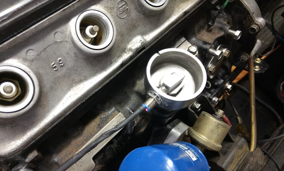
Cam Position Sensor MkII for a K Series Engine: So ! gutted a 3K dizzy completely, so that it was just a shell. No vacuum function, or bob weights etc. All gone. Cut the centre shaft right down, & pressed a small aluminium block onto the centre shaft top, so I could drill a 3mm hole horizontally to mount a tiny 3mm dia. rare earth magnet. (Glued & pressed in to a slightly undersized hole) Cut the alloy case of the dissy, in half horizontally, to reduce it's size. Drilled a hole in the side of the case, to line up with said rare earth magnet, & there you have it. The Hall effect device, will run on any voltage between 6-36V dc. It has a little LED on the rear end of it, so it is easy to check it is working. The barrel of the Hall Effect device is threaded, so it is very easy to set the gap between magnet face & Hall Effect sensor, which is not critical. The pulse is a good width, of about 20 deg. of the rotation of the distributor, which means it is on for about 5.5% of each rotation. Put a lid on it, which I'll add a couple of clips on the dizzy casing, to hold it in place. Will probalbly use the clips that held the dizzy cap on originally. Yes, it does say "ORANGE" on the lid, as I raided my wife's jam jar cupboard, whilst she was out shopping, & found a lid exactly the right diameter. About 2 hours work, & just a sensor that comes in under $ 10. How simple is that ! Cheers Banjo
-
Thanks Frosty ! Got it. I actually had that one, which I had acquired off the internet some time ago, but it had been laboriously scanned by hand, & the diagrams were very unclear. The one you posted, is much, much better. Thanks again. Cheers Banjo
-
Try this link . ..https://www.ebay.com.au/itm/152829741432
-
Thanks for that photo of the innards of the 4AGE dizzy. I must admit, I've not seen a 4AGE dizzy previously. The 4 tooth, top trigger wheel is like the conventional points, & fires the coil in the normal way, & distributes it to the spark plug via the rotor. The bottom 24 tooth multi-tooth wheel, is I presume representing the crankshaft position. I notice a missing tooth; but maybe there are two missing teeth, on opposite sides of the wheel, as the dizzy does one revolution, for every two of the crankshaft. Some Nissan dizzies had a similar arrangement, that used punched S.S. disks with light sensors either side of the disk. There were two circles of punched holes. Again one was for the cam/dizzy position, & the other for the crankshaft. Few, if any manufacturers use that method now. The most accurate way, to measure both engine RPM, & crankshaft position, is off the crankshaft itself. The problem with trying to measure crankshaft position with the dizzy; is that inbetween the crank & the dizzy, is either a chain or a belt, & then there is the gear off the camshaft, to dive the dizzy. All opportunities to introduce angular errors. (We all know, how much slop you can get in a K series camshaft sprocket chain). https://www.efignition.com/c-3632495/crank-position-sensor/ My first experiments started measuring the flywheel ring gear, used by the starter. That worked well, but was difficult area to get at, in most vehicles. I believe a few European cars used the ring gear teeth, years ago. Probably the French, as they are always a bit different. The camshaft position sensor, only provides one (1) pulse per two (2) revolutions, of the crankshaft. It doesn't worry about a bit of slop in a chain or belt, etc, as it's only purpose in life, is to let the EMS/ECU know that the next cyclinder to reach TDC, is going to be cylinder no: 1. ECUs are programmed with the firing order, so once the cam position, advises which cylinder is next to fire, the ECU can work out the firing order from that point on. So tonight I'll be cutting a 3k dizzy case in half, & see if I can't attach a rare earth magnet to the "locked up" shaft, & put a Hall Effect snsor through the side of the case. Mind you; we don't want anythingm like this "over the top'" type crankshaft trigger wheel, on a Rolla. Cheers Banjo
-
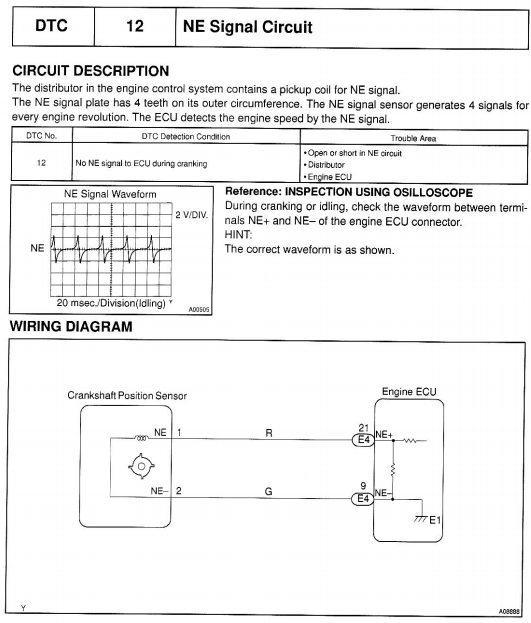
I think the 7K EFI setup does the same thing. when I take a close look at this "fuel pressure regulator", mounted on the end of the fuel rail, it does have a small push on rubber hose fitting, which goes back to a point on the inlet plenum. I have got hold of a Toyota 7K workshop manual, & the specs say the fuel pressure regulator operates in the range around 38 PSI. That all makes senso now. I'm going to fit a fuel pressure guage on the fuel line into the fuel rail, at the opposite end, so I will be able to easily check that the regulator is working or not, by applying some vaccum, to the little hose to the regulator. I've never actually seen a 7K engine complete, in the flesh, so maybe someone on here, that has a 7K-EFI could comment. Not quite sure how the 7K-EFI ECU gets it's cam position information. The 7K used a standard sort of distributor, so the actual HV spark to the spark plugs was distributed in the usual way. The manual talks about a NE signal. Not sure how four points on the crankcase let you know where the camshalf is positioned. Although called a crankshaft postion sensor, it is actually sited in the distribuor itself. 4 pulses in the distributor, would produce 4 pulses for every 2 crankshaft revolutions, which is a full cycle. The 7K EFI has 4 off injectors, unlike I belief, the 4K-EFI, which used a single injector, & sort of batch fired. There are a couple of ways I can produce a cam position senor output. The 5K I did it on, was off the camshaft chain sprocket, which worked well, but it requires the timing chain cover to be removed. I then tried using the lobe on the cam shaft, for the fuel pump, (which I am not using), as a camshaft position pulse generator. It worked, but was a bit borderline, so I diced that idea. The dizzy shaft is the best spot, as even if you abandon the dizzy altogether, you still need the shaft to turn the oil pump. On the 5K I just made up a dear little dummy shaft, by cutting one off, below the distributor, & putting a little cover over it, to retain the oil sealing. I may do exactly what you suggest, by putting a single rare earth magnet off the dummy shaft, & pick it up with a sensor. On my KE30, I have been running a 3K dizzy for years, very reliably, with a Hall Effect elctroniic sensor & ignitor. They simple replace the points, in a standard dizzy. I just loaded the ignitor output with a 100 ohm resistor, & used that single to feed to the ECU. I could easily do that, & only leave one lobe on the "rotor" piece, so it generated one pulse per dizzy revolution. Lots of possibilities there, so will have a play later on today, as I already have a "gutted" 3K dizzy here on the bench. I like the 3K dissy, as they were the smallest of all the dizzies, fitted to K Series engines. Cheers Banjo
-
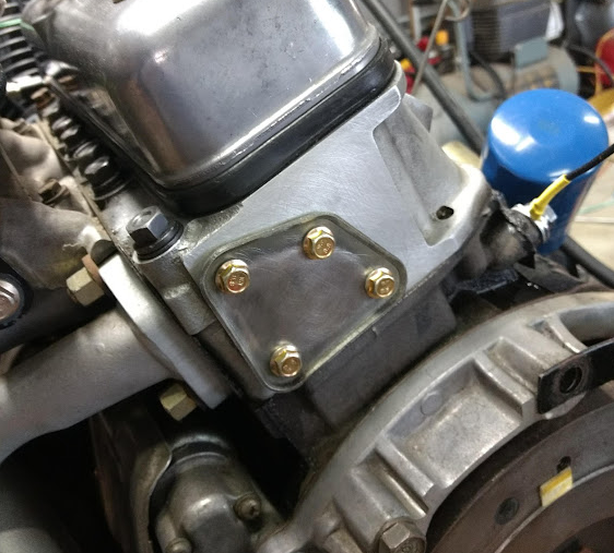
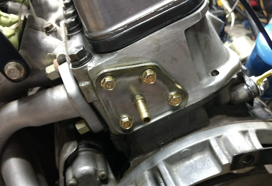
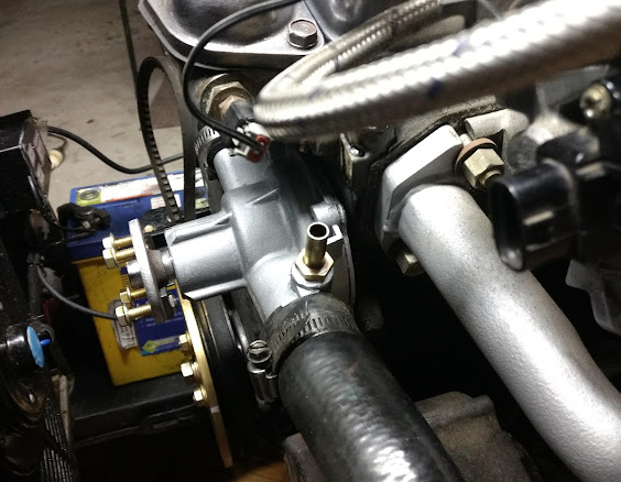
In Brisbane, with only a few days of winter left; yesterday was a beautiful day to spend in the "the shed", as my better half calls it. Before I'd even read your post, Keith, that is exactly the conclusion I came to, & what I did. There are lots of reasons why it is good doing this type of mods to the engine "out of the vehicle". Access is great, when it is on a test stand. The plate on the back of the head, can be a pain. The four small 6mm bolts holding the plate on, often become rusted & break off. When you get the plate off, the water jacket, in that area, is often full of corrosion & build up. I was very lucky, in that all four (4) bolts came out easily, & when the water jacket was exposed; it was as "clean as a whistle". I had never had this 4K engine apart, so it was obvious; a previous owner had; so I was lucky. Even the back of the plate, where it is exposed to the water jacket, is often pitted & thin; but this one had little pitting, with plenty of metal thickess left, to fit a hose fitting. I found a hose adaptor fitting in my box of junk, the same as the hose fitting on the IAC valve, so I could simply run the same hose, from one to the other. The return run from the IAC valve, to the water pump inlet, is quite short. However, the spare inlet point on the water pump; adjacent to the radiator bottom hose connection, is far to large, for this particular modification. I eventually, cut the casting spout off altogether, & because there is a lot of metal in that area, I drilled it out & threaded it; & again fitted a brass hose adaptor, for the 5/16" hose I intend to use. It did involve removing the water pump, so I could hold it in a vice, on the bench, but I didn't have to remove the radiator, to get at it, which is something, that would be difficult, if the engine was in the car. So off to get some hose today, & that ticks that job off. Will have to await, until the engine is running, to see if the IAC valve action, performs, as anticipated. On the front end of the fuel rail, on the 7K-EFI setup, there is a device, that I'm assuming, is a fuel pressure regulator, with a threaded hole, which I assume is the return fuel line to the fuel tank. There is no obvious adjustment possible for the regulator, so maybe it is non adjustable. I might just plug it off, & fit an external regulator. Someone on here, who is more familiar with the 7K-EFI setup, might be able to put me straight there. I have already fitted my trigger wheel, using a 150mm dia. aluminium disk, with small rare earth magnets embeded, which worked so well on the 5K engine. All I need now is to produce a cam position signal; so that is the next job. Cheers Banjo
-
That description is as good a simple description, that I've seen. It doesn't mention coolant temperature control, using either a wax chamber, or bi-metalic spring; but could also use that same function; as the ECU measures & monitors coolant temperature. The beauty of the DENSO one I'm using, is if the signal from the ECU fails for any reason, you still have an adjustment on the trottle body; to crack open the throttle butterfly, to supplement the initial bypass valve opening, so that the engine will idle initially, with the temperature at cold start up. I think is called the KISS principle. Keep It Super Simple. The only thing I would question in the description, in your link, is the statement . . . "This makes the plunger inside move forward and backwards very quickly." In practice, the "plunger" maintains a relatively stationary position for a partular mark/space (On/Off) ratio. If the plunger was flying backwards & forwards very fast all the time, it would werar out in no time. In practice, the electrical signal from the ECU, changes very fast, but magnetic forces & the inertia of the plunger magnet don't; so it tends to find a steady spot, somewhere inbetween full open, & fully closed, based on the electrical indiced magnetic force, applied to it. That is why the frequency of 100-300Hz is chosen, so that it's time constant, is faster than that of magnetic field. This afternoon, I've been looking at where I will run the coolant hoses to & from, the IAC valve. The plate on the back of the head would be a good starting point. That's where there is take-off point, for the heater. A good return point, would be the thermostat housing on the 4K, which has one large entry hole. However, that position, is on the backside of the thermostat, so maybe, on startup, when the engine is cold, & the thermostat is still closed, that would not create much flow, in the coolant line to the IAC valve. There is a small pipe on the water pump (inlet side), so that may be a better spot. I have actually come across a top spout & hose connection point housing, which covers the thermostat, which has a flat on the top, where a return line could be connected to. However, that results in the return water going through the radiator, when you really want the engine coolant to warm up as quickly as possible. "Proof will be in the pudding", & I can always measure warm up time, & change connection points for the best result. Cheers Banjo


