

Banjo
Regular Member
-
Joined
-
Last visited
Everything posted by Banjo
-
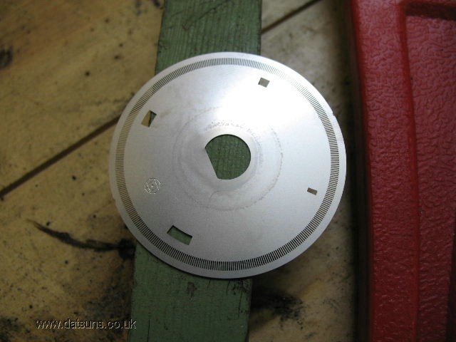
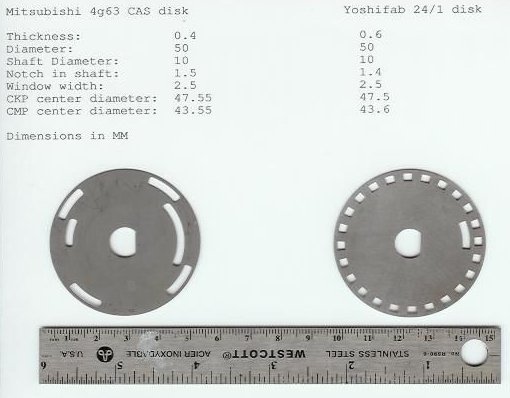
Hi Geoff, Yeah, the home style EFI conversion video was a bit addictive. Glad to see there is some else on Rollaclub, who is really interested in EFI conversion on a K Series engine. I've played with all sorts of triggering systems, over the years. Haltech Video on Crank & Camshaft Toothed Degree Wheels The simplest thing you can produce, if you need a distributor "degree wheel", with missing tooth, is build one yourself, using an old Corolla dizzy, & locking it up, & adding a Nissan degree disk. Here's one I made a few years ago. The trick is to use the Bosch dizzy, rather than the Denso dizzy. The Bosch dizzy, fitted to many later K Series motors, was physically bigger in diameter, & can fairly easily squeeze in the mechanism, from a later model Nissan dizzy. The Nissan dizzy, has an optical sensor, & a number of different stainless steel disks available, including missing tooth. Here is another setup I found on the net, that someone was adapting to his engine. Don't really know, from where it originates. Mitsubishi ? Nissan ? Sometimes easier to mechanically adapt something, that already works, to your application. Some one on here might recognise it ? Really easy to lock up the Rolla dizzies, by taking out all the springs & bob weights etc. There is a guy in Sydney somewhere, who can laser cut or punch out these disks, in any format you need or want. I know Adrian (Nesta/Rollaclub) got one a few years ago, when he was playing around with 7K EFI systems. I might have a couple of S.S. disks here lying around, if you want to have a go, at making one yourself. Several months ago, I raised a query on here, that I heard that Mazda produced a EFI Carby type thingo, on one of the 1300 cc engines, that might well adapt to our engines, being of similar capacity. I believe it is a Mazda B5-ME series motor, with EGI SPI. I have yet to see one in the flesh, & haven't had time to crawl the wrecking yards, looking for one. Like the Kia Corolla video, it would be a relatively simple way to add EFI to a 3K or 4K engine. From memory, it apparently takes the simple bolt on format of the Holley conversion, but without the "smarts". I presume Mazda had a little "box" to control it. Cheers Banjo




-
Hi Colin, Despite our old Corollas, only having three (3) engine mounts, two (2) off them counteract, the thrust motion of the engine trying to "roll", or twist. From my observation, the engine mount on the inlet & exhaust manifolds, takes the most thrust load, "in extension" (tries to tear it apart). This particular engine mount, suffers more than most, because the rubber in the mount, is so close to the exhaust system, & the heat generated from there. That's why Toyota, included a little heat deflector plate in the engine mount. Unfortunately, it was attached with pop rivets, & often after years of use, becomes loose, & fall off, or rattle. If any one of the three (3) engine mounts fail, it is usually the rear gearbox one. This one usually suffers from oil leaks, at the back of the gearbox, & separates from one on the mounted metal pieces, that make up the mount. However, even a failed one, does not effect the roll or thrust movement of the engine, to any great extent. The Echo 2NZ-FE engine only has 3 off engine mounts. The two (2) at the ends of the engine, (East / West), which don't resist the rotation thrust of the engine, very much, when releasing power. This thrust movement, is taken up, by just one mount, at the rear of engine, in a "compression" mode. There is no engine mount on the front of the engine, behind the radiator, in most East/West engine configurations. However, the third engine mount that does most of the work, to counter engine thrust rotation, is well spaced away from the engine, so has a large effect, as a result of mechanical advantage. However, in most East/East engine arrangements, like the Echo, this engine mount is very close to the exhaust system, & the heat shields in this area are usually, pretty extensive. I had two (2) off the three (3) engine mounts out, whilst I changed the clutch, & both were in excellent condition, so I don't think, that the slight shudder I've experienced, is the result of engine mount deterioration. I'll let you know, if bleeding the clutch, has the desired effect. Cheers Banjo
-
Hi Adrien, Welcome aboard ! Where are located ? I have a 1974 KE30, here in Australia, that was assembled by AMI in Melbourne. It has the traditional KE Rolla bonnet, shape, & has the chrome air flow grills at the back. I have some body parts from my 1979 "deceased" KE55 2 door coupe, (died of cancer) which had the bonnet with the front raised lip on it, but its air grills, were simply pressed. (no chrome insert) The KE55 coupe was very similar to your KE35 coupe. Interestingly, the 3 bar chrome grill you have there seems to be much wider than the 2 bar one on my KE30. I don't think it would be too hard to cut out your bonnet, & insert the chrome grills you have acquired. Have you just acquired your KE35 ? Cheers Banjo


-
Came across this video, as you do when there is a pandemic in progress, & you have time to chill. https://www.youtube.com/watch?v=y2x25ga1MSg It's from California, in the USA, & is the first in, a long series, (Not as long as Project Binky ! https://www.youtube.com/channel/UCHvBHWBzzB7NyU5tIiEZHBg), but shines a light, on a different approach to fitting EFI to carburetor engines. The Holley Sniper system, is expensive, by Australian standards, but is relatively simple, to implement. Holley also have an ignition module, that mates to the EFI carburetor replacement device, so that you finish up with a pretty easy system refit. P.S. Got a bit bored during the rerunning of fuel lines section, from back to front, but somehow, the video was infectious, & I kept watching. Note: The background music might put you to sleep ? P.S.S. Oh by the way, . . . . . . these guys have never heard of our product "Start You Barstard" P.S.S.S. I think project Binky is up to about Episode 30 now. I'm starting to get worried, they may not get this project finished, before I depart this planet. Cheers Banjo
-
Hi Keith, Since posting that yesterday, I've done a little more research, & found numerous references to clutch shudder on Yaris websites & forums. (Yaris use the same engine family as the Echo) There are informed comments on there, that the shudder incidence is wide spread, & can often be solved by completely changing the brake fluid, & bleeding both clutch & brakes. These model Toyota share a common reserve fluid tank, which is very hard to access, so doesn't get done often, or gets put into the "too hard" basket. I'm not discounting it, as "stranger things have happened", but I feel absolutely no "sponginess", in the clutch pedal. So what's to lose; so I'll try bleeding at the weekend, & see what transpires. P.S. I take your point . . . . . "or the shafts are shorter in new g'boxes, or a design change internally keeps the input stable." The shaft is certainly a bit shorter. Cheers Banjo
-
I'm not a professional mechanic, but have played with various engines & drive trains over the years, (mainly Toyota), but recently came across something, that has me scratching my head ? I'm very familiar with the spigot or pilot bearing, that supports the front spigot of the gearbox input shaft, which is notoriously hard to remove sometimes, but can be accomplished with the grease/wet paper/white bread/compression technique. https://www.youtube.com/watch?v=Wvg5YtB4CQ0 I've always replaced the spigot/pilot bearing, anytime I've had the gearbox or clutch out, as it is not the place you get to often, & can become annoying if it wears out, or goes dry & squeals. I am well aware of the need for the spigot bearing or bush, to keep the input shaft of the gearbox completely aligned, so that there is no shudder in the engagement of the clutch plate, which is directly "tied" to the gearbox input shaft via 19 or 21 splines, in our K series combinations. KE Series Gearbox Input Shaft This is borne out, by the fact that I have a 4 & a 5 speed K series gearboxes on my garage floor atm, & if I move the spigot point on the gearbox input shaft with my finger, there is some slop in it up & down, (couple of mm) which is "unwanted", in operation. There is movement, because there is a "single" front gearbox bearing, at the other end of the shaft, behind the front gearbox oil seal. As this front bearing wears a little, any movement in the shaft is "amplified" because the spigot point is so far removed from the bearing mounting point. So I bought my kids a 2004 Toyota Echo Hatchback, a couple of years back, which is a great little roundabout, with extremely good economy. (700+klms to a 38 litre refill) The clutch had a very slight shudder in it, when I bought it, so got a couple of hundred bucks off the price, when I purchased it. I ordered an Exedy Clutch replacement kit, with everything included, like throw out bearing etc. I've actually never taken a gearbox out of an east/west engined car previously, without removing the whole engine & gearbox, as a complete unit. I also unfortunately don't have a hoist. However, there is always a way, & to cut a long story short, the gearbox came out OK, along with the clutch & pressure plate. What I then saw both surprised me, & concerned me. The Echo engine had no spigot/pilot bearing at the back of the crankshaft/flywheel. The input shaft for the gearbox, had no spigot turned down point on the tip of it, which is usually how they look. I had never come across this before, but with researched since, have discovered that there are other more recent Toyota engines, that also have no spigot bearing or bush. So I put the new clutch in it, & put it all back together, & everything went well. So my son has been driving it around Canberra for a year or so now, & I recently traveled down there, from Brissy, & took a Yaris to him, & drove the Echo back again, to be used by my daughter. I have noticed again that there is the slightest shudder, when taking off from a standing start in 1st gear. As the clutch is fairly new, & the flywheel face was very clean, when I put it back together, I can only assume that with 180K klms on the car, the front gearbox bearing, has a little wear & movement in it, which is allowing the other end of the shaft to move a bit, under take up. I have no idea at all why the spigot/pilot bearing was "abandoned" in the design of the Echo 2NZ-FE engine & others ? Has anyone else on here come across this before, & experienced similar movement shudders ? The only way I could see the designers removing the need for a spigot bearing, was if there were two front bearings in the gearbox, spaced slightly, or maybe one very wide bearing. As I said, "Got me scratching my head ?" Your thoughts or theories ? Cheers Banjo


-
Hi James, Here is a very "olde" post (2012) on our forum, that might be of help to you in other areas, although not specific about "slant" & "flat face" bonnets. https://www.rollaclub.com/board/topic/62425-the-noob-starting-guide-to-ke70s/ Here's another post which votes on which bonnet is best (once you get to page 3), but doesn't provide anything useful regarding dimensions, which Altezzaclub has already advised. https://www.rollaclub.com/board/topic/40183-slant-vs-flat-front/#comments James, there is a guy advertising on Gumtree, in Port Arthur, who has a lot of KE70 body & window parts for sale. Cheers Banjo
-
Hi Dave, Rattle, rattle, rattle ! Biggest problem with "rotary" electric fuel pumps, is definitely, the noise & vibration. I only fitted one to my Rolla, so I could use a mechanical fuel pump, "modified", to experiment with as an easy way to produce a synch pulse, from the fuel pump lobe on the camshaft, for my electronic ignition system. There are in-tank electric pumps with low pressure outputs for carby engines. https://www.hotrod.com/articles/aeromotives-tank-pumps-carburetors/ The great beauty of an electric fuel pump, is that they can be fitted at, or near the tank, so that the majority of the fuel line between tank & carby inlet, is under pressure, not vacuum. The other electric fuel pump, that is electric, but not rotary, is the British SU, as fitted to many early English cars. These produce a tick, tick, tick, rather than a rattle/rattle/rattle. Plenty of these available second hand, & you can still purchase repair kits, & recondition one. Biggest issue with SUs, was the "points", which like our Rolla dizzy points, used to burn, & pit, & stick. I note now that these SU points, can now be fitted with a solid state electronic "points", which overcomes this problem. However, many of the early British cars that used SU electric fuel pumps, that were imported to Australia, had the SU attached to the firewall in the engine bay, & the line from the fuel tank in the rear, was under suction. Worse than that, these English cars ran their fuel lines parallel to the exhaust system, to keep the petrol warm, in their northern hemisphere winters. Unfortunately, in Australia, that created vapourisation in the fuel line, & the solution was to fit the SU in the rear of the car, & reroute the fuel line, away from the exhaust system. I used to have an olde SU fuel pump here somewhere. My Dad used to have a Morris 6, in the early days, & could remember, often having to get out of the car, lift the bonnet, & give the SU a good few taps on the side, to free the points from sticking. https://www.mgexp.com/forum/mgb-and-gt-forum.1/su-or-hardi-fuel-pump.3251831/ There are a couple of German brands of electric fuel pumps, in the SU vein. They are the Hardi & Huco. Here is a video with some good basic advice & formula, for sizing. https://www.youtube.com/watch?list=RDCMUCI3fKpfLBb9NegrWPWI2k_w&v=O06TpVafwIo&feature=emb_rel_end Cheers Banjo
-
Hi James, Try this basic one for starters. https://www.youtube.com/watch?v=2ilRYuGcPkI ebay cheapie ! They work, but need to be isolated mechanically of rubber mounts. Cheers Banjo

-
Hi James, There is a very simple test you can carry out, to see whether the issue is the pump itself, or the fuel line between tank & filter & pump. Get a couple of metres of suitable size clear plastic tubing. Slide one end over pump inlet spout, & stick the other end in a can of petrol, which is sited local to the engine. Run the engine, & watch the petrol delivery through the clear plastic tubing. There should be no bubbles evident. If the tube end is always held below the level of petrol in the can, then there is no chance of any air being introduced. If the engine is still starving, or running out of fuel, you might want to fit another bit of clear plastic tubing, between the pump outlet & the inlet to the carby. If there are bubbles in this line, then there is a problem with the pump diaphram or internal valves. If there are no bubbles, but the problem persists, then it likely to be in the carby itself. Likely suspects are the inlet ball/pin valve, or the carby float. The most common problem is a blocked carby inlet filter. Many users don't even know there is an inlet filter in the carby, as it is not visible. You actually have to remove/unscrew the inlet valve assembly, & then pull it out. It is a very, very fine gauze filter, & often clogs up over time. Clean this filter, & if that was the issue, your problem will be eliminated. If you still want to go electric pump, give us a yell, & I'll post a picture of a very cheap one I picked up on ebay, that works well, although a bit noisy. Cheers Banjo
-
Hi James, Welcome aboard ! Are you looking for a mechanical pump to replace the OEM one one the front LHS of the engine, or are you toying with possibly, switching over to an electric pump, which has some advantages, & disadvantages ? The original OEM pumps were very reliable, but asked to suck fuel from a long way back. I once had a mechanical pump that would not deliver. After trying two other pumps, with the same results, I came to the conclusion, that my issue was not the pump at all. Issue was a not perfect seal in the fuel line, that was almost undetectable, but pushed the pump beyond its limits. Only found it by running a long piece of plastic hose from the tank to the pump input. It worked perfectly, so hence I went looking for the point, where it was sucking in air. It you go electric, & mount the pump in the rear of the car, this has the advantage, that the suction line is short, & the bulk of the fuel line from the back of the car, to the carby inlet, is under pressure, not vacuum. However, the disadvantage is, that you must add some safety features to ensure the pump is powered down, if the car is involved in an accident. Lets know your thoughts. Cheers Banjo
-
Hi Graeme, For you ! For the Love of Toyota's 86 Corolla is Eternal Cheers Karlos
-
Hi Karlos, You left your "location" on in your camera, & using the latest hi-tech software, we have here in Oz, I was able to locate you in South America, & pick up a picture of you in real-time, from a road side camera. I have very bad news for you. Your beloved Corolla, has already contracted the viras, & turned into a Corona ! As for the olde paint drum you used to store the old sump oil in, I can advise, that "Acid" is not a colour name for some Toyota Colour Code. One other thing I noticed about your car, that you may have missed. The hubcaps have fallen off; although there are others on our forum, who would probable suggest, that is the least of your issues with your Corolla. We are amazed at the amount of work you have done to the car already, & ask that you regularly put some more pictures up here for us to look at . . . . . . . once you get your camera working again. Cheers Banjo

-
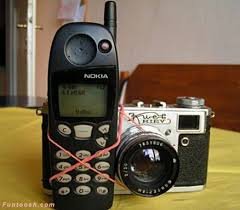
I'm new here. I live in South America. Found your website, as I'm scared about my KE Corolla, catching the viras, & turning into a Corona. I do not want that, as I couldn't afford to pay for the more Benzine it would use. I have looked up about the viras, & found that the Corona Viras sticks to metal surfaces. I decided to make my Corolla very slippery, so nothing could stick to it. I poured an old drum of sump oil, I had here, all over it last night, before going to bed. Very bad ! When I wake up this morning, the paint is peeling all over my Rolla. Is there anything I can do to reverse this condition ? P.S. Sorry, I can't post a picture of it, as I think my phone has got the viras too, as the camera part doesn't seem to be working this morning. Thanks Karlos
-
Hi Chauny, Welcome aboard ! Bet we can help you fix your Corolla, as there are not too many faults, I would think, that we haven't come across before. (especially electrical) Altezzaclub, was quick to answer you, because he "loves" KE70s. Tell us a little about your Corolla, which will help us, help you. Electrical faults can be intermittent, or "partial", but are often, just working one minute, & not the next. (like when you blow a fuse) When was your Corolla last running OK ? Did it just stop, or was there signs of something going wrong before it became immobile ? Any smells ? Dim lights ? Been hard to start ? The more information you can feed us, the quicker we can point you in the right direction, & get you mobile again. Cheers Banjo
-
Hi Mason, From one woe to another, it seems ! As the replacement alternator you obtained was a "new" one, & it is not charging properly, your best option, is to now change the external regulator, if you can get hold of one. I would suggest to any one who is going to fork out for a new alternator, that they upgrade it to one with more output, & that has an inbuilt solid state regulator. The original Corolla factory alternators all had outputs of 30-35-or 40 amperes. Current alternators with 85A output are of similar size, & you'll always have nice bright headlight, instead of the "yellow candles". Although there are plenty of 85A & upwards alternators available, mounting them is the big issue, & lining up the pulley that the front, with the existing water pump, & crankshaft pulleys. I used an 85A one out of a earlier model Toyota Hilux, years ago, & it has be fantastic. It wasn't even new; it was a rebuilt unit. I only recently had to replace the regulator, which started to play up. The reason the Hilux alternator was a good substitute, was that it fitted on the existing K Series engine alternator mounting bracket, & only needed about 3 washers to move it, forward, so the pulleys lined up. I think I even transposed the original alternator pulley. Hope that is another option for you. Cheers Banjo
-
Hi Mason, Is the alternator causing all your woes original ? Does it have an external regulator up on the firewall somewhere, or is it an alternator, with a built in electronic regulator ? You seem to indicate that the car was running with a "blown" engine fuse, which seems a bit odd, as usually the engine fuse powers the ignition coil ? Does the car wiring give any indication, it might have been hacked, or changed at any time in it's life ? Cheers Banjo
-
-
Wow ! Usually my hands are dirtier than the spark plugs. In your case, it is the reverse. Your hands are a darn sight cleaner than the plugs. If plugs are like that, it could indicate no regular maintenance has been done on this engine for a while. When you picked it up, had it been sitting unused for a while ? I'd be getting the oil out of the sump quick time, & getting some new oil in there, with new oil filter. Then the "compression test", is a must, before you do anything else, as others have advised. (don't forget to run the engine to operating temperature, before doing the compression test) Remove all spark plugs before doing the compression test. If the resultant pressures come in down around the 130 PSI mark, put a teaspoon of engine oil in each spark plug hole, & repeat the test. If pressure figures improve significantly, then the lower compression could well be the piston ring & or bore wear. If the added oil doesn't improve readings, then it is time for the head to come off, to check the valves & seats. Keep us up to date, with what you find. Cheers Banjo
-
Hi Daniel, What an amazing find ! Very, very rare to find a KE-20 is what appears to be absolutely fantastic condition. Would love to hear the history you have unearthed behind the car, & the circumstances of how & where you located it. There'd be a few people on this forum, that would be drooling at the photos you have posted. I'm presuming the auto gearbox in it, is a 2 speed ? Can't work out quite, the white vinyl roof ? Did you add that, or did it have it when you purchased it, & you've removed it since ? Looking forward to watching your upgrading of the engine & drive chain. What plans do you have for upgrading the brakes ? The KE-20s were never known for their braking prowess, & with the greater HP, you'll certainly have to give it a bit more "stop", as well as "go". Cheers Banjo
-
Watched the latest episode of Project Binky last night, which is Episode 29. Thought I was going to see the shell return from the spray painters, all shiny & new, only to find, that those guys had found something else to completely pull apart, & refurbish. I really wish, they would get this project finished. It's a bit like watching grass grow ! I shouldn't complain though, as many of us have pet projects, that go on for years. Cheers Banjo
-
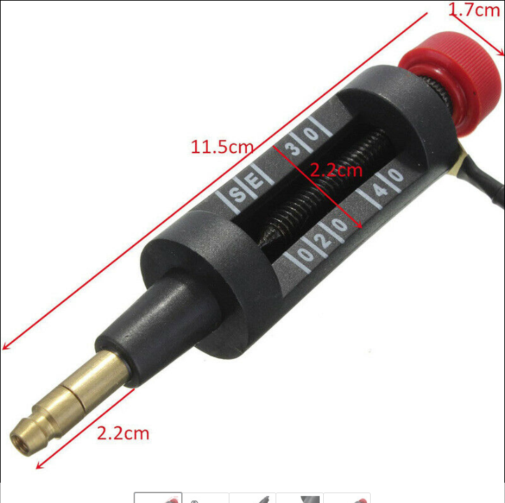
There is already an air gap at atmospheric pressure, between the ignition coil tower & the spark plug, even when the carbon button is "present". It's the small gap between the tip if the dizzy rotor, & the four (4) pins in the dizzy cap. i suppose you could grind or file away the end of rotor metal "finger", and create an air gap of some magnitude, if needs be. However, the metal either side of the gap, really needs to be something hard, that will resist those billions of electrons burning & transferring metal to the other terminal. You can see the buildup on the dizzy cap inner pins in the picture above. I did notice on the rotor button, that was working, when there was no carbon button, in contact with it, that there was already signs of metal movement away from the area, where the button, would normally rest, & create a round shiny area. (see pic below) You can buy on ebay, a simple device for creating an adjustable air gap in your HT line from the coil tower. I've used one in the past to test a suspect coil. You just turn the knurled knob, & make the "spark air gap", larger, until the coil cannot create a voltage high enough to "jump" the gap. Those markings represent 20, 30, & 40kV. the 40kV gap is about 20mm. I've also used it, to adjust the dwell (time period the current flows in the coil primary winding), so that the coil just saturates, without wasting additional energy or heat, that won't improve the performance, of the coil, any further. Cheers Banjo


-
At the weekend, I gave the engine a quick spray with the degreaser, left it a few minutes, then hosed it down. Normally the engine starts up straight after this, as I am careful where I direct the hose nozzle. Anyway, this time it didn't start, so off I go looking for the issue. Turned out in the end, to be water inside a supposedly "sealed" standard 30A automotive relay, I use to supply power to my high energy ignition coil, so the higher amperes, don't run through the ignition switch. Anyway, replaced relay coil, & located it a bit higher up in the engine bay. However, while checking things ignition, I lifted the dizzy cap, to see any water had ingress'd in there. Imagine my surprise, when i discovered there was no carbon button poking out of the centre of the cap. Well there was, but there was not much left of it. The Bakelite around the hole where the carbon sits was all broken away, as seen above. Normally, a fault like this would cause all sorts of problems, but my engine had been working perfectly. It then struck me, that because I have a hi-energy ignition coil capable of probably 40-50 Kilovolts; that when the carbon button worn down, it just continued to jump the small gap, & then eat the carbon button away. The gap between the top of the rotor button, & what's left of the carbon button, is around 4-5mm. I had another 3K Denso dizzy cap, so grabbed it, & swapped it over. Was just about to throw this above cap in the rubbish bin, when I had an idea. If it will jump a gap that big, in atmospheric pressure, then why do I need a carbon button at all. The cap was not reusable, because the centre hole was so broken away. What if I put a solid metal rod down there that finished flush with the end of the hole. A quarter inch gutter bolt was just the right size. It was just a little too big in diameter, that it screwed nicely into the Bakelite dizzy cap. I then filed the thread end of the screw, so that when it touched the metal in the cap, at the bottom of the hole, the underside of the screw top, was flush with the end of the hole. it was then just a matter of filing the domed head of the screw, so it was clear of the metal on the top of the rotor button. So popped it back on the car; started up first pop, & took it for a drive, & it worked perfectly. So it's back in the boot now, so if I'm ever caught again with a broken or worn rotor button, I'll just swap the cap over, & be on my way. Reminded me of a story I once heard, that dirt track speed car guys, used to build a gadget with large plastic buttons, spacing the hi-tension leads on the cap, to produce an air gap outside the engine, that created a bigger spark across the spark plugs. Don't know how true the story is, but my little experiment, indicated that you can certainly generate a higher HV out of the coil, if the spark jumps a bigger gap, outside the combustion camber, before it jumps the spark plug gap. Cheers Banjo


-
Hi James, Have you put the car on a flat concrete floor, & measured the camber that has resulted from the lowering ? Even if you don't have one of those little electronic inclinometers; with a straight- edge across the rim edges, in a vertical plane, with a spirit level, you should get a good idea. If you take Colin's advice, & get a wheel alignment, the camber & caster angles will be measured, as part of that service, & will be noted on your report. What are all the rubber bushes, ball joints, & steering pivot bushes like on the front end ? The McPherson strut design was cheap to manufacture, but does have some nasty results, if everything is not just right. Gets even nastier, if you start changing the geometry dramatically. Cheers Banjo
-
One of the “perennial” problems with our early Rollas, is the adjustment of the clutch cable. Perennial “lasting or existing for a long or apparently infinite time; enduring or continually recurring.” Now I hear some of you suggesting, “well just go hydraulic”, but that is usually implemented by those, that have upgraded to a gearbox, that is hydraulically operated. There are posts on this forum, with various adaptions of the clutch pedal to hydraulic, but they are not for the faint hearted, & the fact that the cable pulls, & the hydraulic pushes, to operate the clutch, does not help. So I’ve decided to stay with the clutch cable, & here is how I have sorted it. The first thing I have always found, is that lubricating the clutch inner cable inside the outer sheath, is extremely important. The cable end to end changes the direction of force through 180 degrees. As it turns the big bend in the engine compartment, there is binding of the inner cable on the inside of the outer cable. I have experienced heavy clutch pressure needed in early days, only to find that extra force required, was to overcome the friction within the cable itself. The fix is simple. Remove the clutch cable completely from the car. Hang it up at one end, from the out sheath. Drip some light oil in the top end, & work the inner cable up & down. Keep adding oil, & continue to “jiggle” it up & down, until the oil starts to drip out the bottom end. (once I had to leave it overnight, for the oil to get to the bottom, on a very tight cable) I even saved a cable for someone once that was literally seized, by feeding WD40 down the cable inner, for 24 hours on & off. The real problem with the clutch cable, is that horrible adjustment design, up on the firewall, with a single circlip, clipped into one of a number of grooves in the cable outer. The circlip is very hard, & the alloy grooved section of the cable is relatively soft. On top of that, when you push the clutch in, the cable pulls down slightly, so the circlip area does not stay flat against the buffer area. Well, early into my KE ownership, years ago, I ditched the circlip altogether & just had a small screw hose clamp around the cable. Actually, I think I had two in "series". Then, I came across a brand new circlip, & decided to remove the hose clamp. Well, it worked OK for 6 months, then one night in the city at 2:00 am, after picking up my daughter, after her restaurant shift, at a set of lights, the clutch pedal went to the floor. I pushed the car back, & searched in vain, for the dislodged circlip. In the end, I gave up, took a hose clamp off the crankcase breather oil collector, & fitted it around the clutch cable, & got home, travelling roads with no traffic lights, so I didn’t have to stop & start. Success, although daughter was not impressed. Anyway, I then decided that’s it; I’ll fix this design issue for good. I finally came up with the idea of using 2 x circlips, & filling the space in between them, so they both effectively shared the load. It was pretty simple really. I fitted both circlips, adjacent to each other, then found a large mild steel washer, about the same OD as the circlips. I then reamed out the centre hole of the washer, so it was the same ID, as the OD of the cable. I then cut out one side of the washer, so it became a “U” shaped washer, that could slip down between the two circlips. It was a bit tight at first, so I placed it on the band sander, until it was just the right thickness, that it could be tapped in gently between the circlips. I was intending to put a drop of Araldite on the washer, so it couldn't turn around & fall out, but 2 months later, it is still snug & tight. The other issue with the clutch cable is, that as you push the clutch in, the force on the circlips, is on the bottom edge, as the cable pulls down. It needs a support on the cable, to hold it pretty much horizontal, for the first 300-400 mm, away from the firewall. I’m sure that a KE55 coupe I once had, actually had a bracket that came off the master cylinder, or thereabouts, to support the cable. No such bracket was ever on my olde KE30. So I rigged up a support bar, to experiment with the best place to support the cable. I’ve now found a spot, so will make up a permanent bracket which will attach to a couple of spare mounting points down on the inner firewall, which you can just see in the fourth picture down. Anyway, it all works well, & the clutch even feels better under the foot, as energy is not used moving the outer cable position. The 180 deg curve of the clutch cable outer sheath, is important. I have noticed over the years, that some aftermarket clutch cables for the KE series are 30-50mm shorter than the originals, which creates a tighter curve, & greater drag, on the inner cable. Hope this description, & associated pics, might assist, & inspire some, to solve their clutch adjustment retention issue, as I have done. Cheers Banjo


