


altezzaclub
-
Posts
6830 -
Joined
-
Last visited
-
Days Won
134
Content Type
Profiles
Forums
Events
Gallery
Blogs
Everything posted by altezzaclub
-
Can't be worse that factory.. They were also on the earlier Great Wall with a Y motor, so the agents should have them too.
-

Ignition timing help. My car wont start
altezzaclub replied to KE70ph's topic in KE70 Technical Articles
Do you still have a distributor in the car? or is that the one you have taken out? Do you want to fit that one?? The big trick is to get the teeth on the bottom gear meshing with the camshaft at the right place, and also getting that slot at the very bottom into the oil pump drive.. As you can see, the camshaft drives the distributor and the oil pump from that one gear. If you have the points inside the dizzy just as they were on a running car, turn the engine to number one cyl top dead center and turn the rotor to line up with number one cyl spark plug. Usually the vac advance diaphram more-or-less faces the front of the car. Slide the dizzy in and give the rotor a wiggle. It should drop right to the bottom of the locking plate, so the O-ring is down in the block. If it doesn't, don't force it, but take it out and carefully turn the shaft about one tooth, then try again. If it doesn't go right in, move it a couple of teeth in the other direction. You can see the oil pump drive down the hole, but the slope on the gears means the shaft turns as you put it in, so you have to start with the slot off to one side. When that it in, turn the dizzy so the points are just opening with the rotor on number one plug lead. Then its easy, once you have number one sorted the rotor fires number 3 next, the 4 then 2, moving clockwise. The middle lead goes to the coil. You might have to swap leads around, so although their firing order stays the same, the starting point for number one cyl might be in a different hole in the cap. It depends on who set the dizzy up last. Mine looks like this-
-
Nah- All four sides are completely different to each other.. Not much space between the cylinders though, just a little strip of metal.
-
That does sound like a VVT problem.. Even worse, when everyone has had a play with everything, you never know where to start!
-
So, hunting around the wrecker checking on projects, I came across one of these- A Daihatsu Move. The reason it doesn't have a disc or hub on that side is because I have them on the bonnet of a nearby car.. They are unusual because the disc mounts on the back of the hub, like a RWD, while nearly all FWD put it on the front of the hub so the wheel bolts it into place. You can see the diameter is bigger by 16mm, or 8mm of radius. The swept area is MUCH bigger, 30mm out to 40mm is a lot. The hole in the middle is 6mm larger (FWD!) so we'd need a 3mm wall spacer to center it. The bolt holes are 2mm out, so that would need a little filing. The setback from the front mounting face goes from 30 to 37 or so, and we can only steal a little of that back. The disc thickness around the hub is only 7mm on a KE70 and 8mm on the Move, so we'd take a mm off that. The caliper mounting holes are15mm closer together, so new mounts would need to be welded onto the KE70 backing plate. The alternative would be to swap the whole plate over from the Move, but that enormouse FWD hole in the middle means the 4 Move boltholes run into the edge when you re-drill for a KE70. Either way it needs a bit of welding for caliper fit. The KE70 holes aren't symmetrical, their pattern is very strange. ..and that is as far as I've got. I don't think I can any check more without doing something about mounting it and seeing if it fits on the strut and if it clears a 13" stock wheel. Anyone with a lathe want to knock up a pair of rings to center the disc? If it fits with a centering ring on the disc and another on the Move backing plate, it would be a very cheap and simple conversion to ventilated discs for stock KE70s, so you can set up a production run later! So, do we need this? Are stock brakes fine? The keen people with fat wallets can go to coilovers and Brembos, others can get Corona/Celica stuff, but I figure the current suspension and steering is nice without adding too much unsprung weight.


-
More trips up and back, running like a dream. I found a worn tie-rod end on one side & replaced that, and one day I'll fit that alloy radiator. Certainly not needed in winter! Been looking at stuff, cheap and simple mods... See how it goes..

-
Sounds like a head gasket problem, letting compression through between two and three.. Very odd... I wonder if they pressure tested the reco'd head. Unless the rings in two and three are destroyed and letting the compression passed into the sump, which would give you major blowby and push oil out the top cover seals...
-
In 16 years time... "The Girl's AE86"
-
If the hollow shaft you can see in the lower photo has a slot up one side it IS the gear drive. They look like this, although these are out of a T50- The nylon gears strip quite often, as you can see with the top one.

-
These guys supply plans if you buy their electronics. Some good tech articles. Seems even retarder chassis dynos need lots of inertia in the rollers, but their bhp figures are way way above what we are looking at. Anything that runs a 100KW 4AGE up to 160kph is great for rallying. https://www.dynomitedynamometer.com/dyno-tech-talk/dyno_hp_limits.htm and the sell the water brakes separately. https://www.dynomitedynamometer.com/absorber/dynamometer_water-brake_absorber.htm
-
The inertial system is easy to calibrate, its just like driving the car on the road with the GPS dyno. You have accelerated a mass of Xkg to speed Ykph in Zsec, and you measure the resistance of the roller bearings with a string and pulley system. But that is all it does, one pull though the revs then slow it down for the next one. The brake dyno can hold the motor at any rpm, but you need either those electrical retarders or the water (or oil) ones, all off heavy vehicles. Mercedes offer water ones on their trucks here, the heated water goes into the radiator and around again. Telma make the electrical ones, but they're all worth a lot of money. I'll look at using a torque converter out of an auto box, its the same basic system. That will measure torque with a load cell OK, but you need to find out how much is lost in the drive. Maybe we can set this up on a roller for a chassis dyno- As for insurance on car work... Hahaha, these guys own KE70s, you don't expect us to get PAID do you??
-
OK, one of the projects on my list is a dyno for Woolshed rallying. Either an engine dyno or a chassis dyno, each have their advantages, but a chassis dyno is handier for tuning a motor in use. An engine dyno is great for building a hand grenade for the future, but not as practical with a handful of KE70s being driven by mates around the town. So I found these guys- http://www.dtec.net.au/index.htm They make the electronics that help your home-built dyno make sense. Amongst their many handy downloads is a dyno designer for an inertial dyno. Basically you set up a roller, put a car on it and give it a power run. The inertia of the roller acts as a limiter on the motor as the car speeds the roller up. It turns out their calculator on "Inertial dyno design tools" says- Maximum speed for the roller set at 1500rpm Maximum car speed to test at set to 160kph Roller diameter 565mm.. or about a 175/75x13" size. Engine power to test set at 100KW Time for dyno run set at 8sec rpm of flywheel at start set to 600rpm (about 2400rpm on the engine) rpm of flywheel at end set to 1500rpm (about 6000rpm on the engine) Inertia required 85kg/m2 This equates to an equivalent vehicle mass of 1065kg, good enough for a KE70. Then it shows you how to calculate the inertia of a flywheel of almost any round shape, I'm thinking of some bulldozer drive wheels lying around... Once you have the roller on bearings it shows you how to measure the built-in inertia of the system. The one above needs a steel roller of 565mm OD, 450mm ID and 1800 long. Except it weighs 1300Kg! Not unexpected, you accelerate a car weighing 1000kg every day, so the roller has to weigh that much. The bearings would have to take that 1.3tons rotating at 1500rpm, about 160kph. Of course if we allow only 6seconds for the pull we only need an inertia of 58kg/m2, so a lighter roller but less accurate. The OD would stay at 565 but the ID goes up to 495. A 60mm thick solid steel tube 1.8M long.. 830Kg. So, not impossible, as an engineering project its straightforward... Anyone else keen? Maybe a brake dyno instead...
-
We have a complete system from a KE70 lying on the floor of the Woolshed, I took it out of the Hoonicorn. You'd have to come on holiday to Walcha...
-
A Bill Sherwood dry sump system might help. Another project on my list to try, it uses the stock oil pump to pump oil around the engine and a single scavenge pump to get the oil up into a remote tank. Then the sump is just a plate below the crank. Give more bhp and eliminates any oil surge problems when cornering.
-
On my list too Banjo, just so handy to have a reliable measure of power at home. Option one would be the water one, there are a couple of youtube vids about one a guy uses. He has a remote control stand set up with starter, throttle, gauges and power dial. It sucks from a 44gal drum and pumps into a pipe that forces the water past an adjustable sprung valve and back in to the tank. Option two is based on the electric brakes on truck trailers. Tip the dual axles upside down and back your car onto them. Then just add more and more resistance as a measure of power produced. One vid on Youtube but it was a bit of fun more than an engineering project. Option three is a handy bit of road with the same start speed each time and a dyno app on your smartphone. All you need is the weight of the car. Sadly the recption is shit around Walcha so that hasn't been very accurate. ---------------------------------------- Found these guys! You build a dyno based on their plans and they sell you the electronics. The inertial system looks worth chasing up. http://www.dtec.net.au/Tech Articles.htm
-
Great! The last reply is always the most important as people with similar problems will read your thread in a few years time and there's nothing more frustrating than not knowing what the solution was in the end!
-
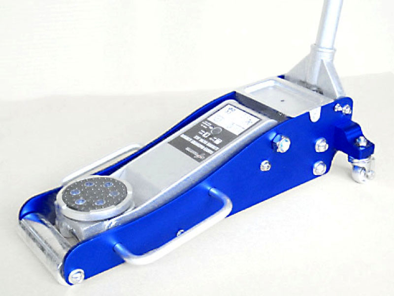
Steve bought one of these off Ebay. Looks just like this, but I don't know the brand. One piston was jammed so it didn't go to full height in 6pumps, so the seller replaced the whole jack. We love it!
-
Wonderful! Now add an auto gearbox torque converter hooked up with water piped through a valve and calibrated for bhp as it pumps the water round and round!
-
Blam! 18years into the future instantly! Great photo!
-
How much clearance are you going to allow around the tunnel? They move around quite a bit over bumps and acceleration. The airbox on my KE70 moves about 15mm upwards as the motor rotates when I let the clutch out. We've got the same box and adapter on the back of a 4AGE, but haven't fitted it yet.
-
All you need is the wire from the tacho to go to your coil -ve, its that simple. Stock wire is black, with a purple extension going around the engine bay to the passenger's side in slanty KE70s. The electronic dizzy has no effect on the tacho circuit. "why are you cutting wires at 3am? " Yes, the time when young men do stupid things!
-
Mx83 Bonnet Gas Struts On Ke70
altezzaclub replied to Grand Master of Awesome's topic in KExx Corolla Discussion
Well, there ya go, only took 7years to solve that problem.. Another 7years of stress testing the mounts and we'll know if it works. -
Steve bought a drill seeder off Great-uncle Neville, so we went out to fetch that. Way to big to fit on a truck.. Luckily Neville is an engineer and had handy things like several 3/4" socket sets! ..and a tractor big enough to lift it! Sadly both the farm tractors are smaller adn lighter, but we got it to sort-of fall off.. That's another giant project to get working in a few years time! So now we can concentrate on emptying the stuff out of the big shed and finally getting a concrete floor laid! Meanwhile we've agreed to service for Leighty in his 240RS for the Orange Rally next month. If you're around look us up!


-
Well, slowly slowly.. Mao has rebuilt Blsteins and Steve has a road car.. Pete's Maxima that everyone borrows has a new LCA bush & doesn't knock any more.. and we did some gardening. Then we sort-of finished the caravan, no water plumbed in yet.. and moved it in by the Woolshed. We finished the steel store except for a door. We made the steel door-frame but haven't found hinges yet...


-
7age/fe build with a twist urgent help
altezzaclub replied to JCSanders's topic in Automotive Discussion
Do we have combustion chamber volumes yet? They will tell you what compression ratio you will end up with, and which head gasket to use. Your capacity is going up 12% on the 4AFE head, so the compression ratio will be too, and if the 4AGE piston already runs at 10.3 you will have 11.6 CR. See what the chamber volumes are on the 4A heads. The hump on the piston will also determine compression ratio and whether or not it becomes interference. The 4AGE isn't an interference motor, judging from when Steve stripped a timing belt last year. We just fitted a new belt and away it went. If the stroke is different then the crank & rods will be different. The crank needs a bigger swing to make the piston go from top to bottom, and the rod must bring the piston right up to the block deck. So as LittleRedSpirit said, get the head and put it on a complete 7AGE block, then worry about it. If you're lucky it will turn out to be really simple.


